• Steel Soldiers now has a few new forums, read more about it at: New Munitions Forums!

  • Microsoft MSN, Live, Hotmail, Outlook email users may not be receiving emails. We are working to resolve this issue. Please add support@steelsoldiers.com to your trusted contacts.

my 24v mess

Wncenergy

New member
42
0
0
Location
Weaverville nc
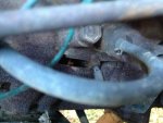
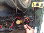
Am I testing them right? I hooked my Positive lead to the positive terminal and unhooked the First passenger side glowplug but got nothing when I touched the negative lead to the plug. Then it struggled to get 8volts out of the green wire connecting into it. Same thing with the next one.
 

jeryshery

Member
80
3
8
Location
winnemucca nv
I would hook positive to the connecting end of the glow plug wire and ground to the engine. If the glowplug controller is working correctly it should cylce between power and no power.
 

jeryshery

Member
80
3
8
Location
winnemucca nv
The resistor changes the voltage from 24 to 12 right before the glow plug relay. So the voltage you should be reading at the glow plug wires should be between 10-13 volts with the ignition on and it should cycle on and off.
EDIT: If the voltage is low I would check all the connections and wires going to the glowplugs for maybe a loose or bad wire or bad connecion. Starting with the positive side of the junction block tracing the wire from there to the resistor. Then from the other side of the resistor to the 12 volt junction block. Then from the junction block to the relay. While your checking all the connections ground the volt meter to the frame then check all the connections with the volt meter. You should get 24v at the junction block. 24v at the resistor. 12 volt after the resistor and everything all the way to the relay
 
Last edited:

ryan77

Well-known member
2,584
56
48
Location
Cary IL
There's no one in your around you that can help?? No ss members close by??? There has to be someone!!
 

Wncenergy

New member
42
0
0
Location
Weaverville nc
I have messaged a few Ryan, till then I know I seem like a train wreck but at least I am having a heck of a time. I will keep coming back in to warm my hands and see what I am doing wrong! Which is the only way I learn how to do it right. Sure am glad ss is around
 

MarcusOReallyus

Well-known member
4,524
811
113
Location
Virginia
The resistor changes the voltage from 24 to 12 right before the glow plug relay. .... You should get 24v at the junction block. 24v at the resistor. 12 volt after the resistor and everything all the way to the relay
You will see 12v after the resistor ONLY when the glow plugs are on. When there is no current flowing, you'll see 24v on both sides of the resistor.
 

Wncenergy

New member
42
0
0
Location
Weaverville nc
How do you test the fusible link with the rubber coating, will the wires fit back in there? Also I have to manually hold up a switch to engage the glow plugs, will I just need to set my multimeter up so that I can see while I hold it or do they still cycle on and off with just the key on.
 

Miah

Member
90
29
18
Location
Kansas City-ish, MO
someone double-check me, but it looks like the resistor bypass has already been done. That red wire which turns to blue is going from the top of the gp relay to the diamond shaped block above it, correct?
 

wayne pick

New member
658
2
0
Location
Valley Cottage NY
I've been watching this thread for a while and figured i'd chime in. The blue to red GP bypass wire does not need a fuseable link in it. The way it's wired, there should be 12v to top lug on the GP relay/solinoid. If not, there is enough red wire to eliminate the blue portion of the wire and the fuseable link. Simply cut the wire on the red side of the link and crimp a ring terminal to it. then go to the 12v bus with the ring terminal.
 

richingalveston

Well-known member
1,715
120
63
Location
galveston/Texas
looks like the bypass has been done and the resistor removed. I should show up in the pick behind the air cleaner but I cannot see it. but yes, the bypass has been done with the way it is wired to the 12volt terminal block. Need to check and see if the fusable lingks are still good. both the one between the 12 volt block and relay and the one from the battery to the 12 volt block
 

Wncenergy

New member
42
0
0
Location
Weaverville nc
image.jpgBeen getting around 8.5v at the wire going into the glow plugs (green) they connect into the thick orange wire which is getting 8.5 as shown. Any thoughts?
 

Attachments

Last edited:

doghead

4 Star General /Moderator
Staff member
Super Moderator
Steel Soldiers Supporter
26,247
1,168
113
Location
NY
What is the voltage going into the relay(top lug) with them powered?
 

doghead

4 Star General /Moderator
Staff member
Super Moderator
Steel Soldiers Supporter
26,247
1,168
113
Location
NY
Your relay is bad.

It is not passing all the voltage due to dirty contacts.

Replace it with the proper relay.

GPR109 or st85

It is a good idea before you install a new one, to test it to be 100% sure it is proper for this system. Simply use your meter and test for continuity between the "frame" of the relay(shinny metal mount area) to all 4 terminal. There should be no continuity.
 
Last edited:

swbradley1

Modertator
Staff member
Super Moderator
Steel Soldiers Supporter
14,206
1,570
113
Location
Dayton, OH
Since you are unsure of how to use the meter....

Continuity is resistance and it is Ohms on the meter. Flip it the resistance and touch both meter leads together and it should read zero. Then do what Doghead said.
 
Top
AdBlock Detected

We get it, advertisements are annoying!

Sure, ad-blocking software does a great job at blocking ads, but it also blocks useful features of our website like our supporting vendors. Their ads help keep Steel Soldiers going. Please consider disabling your ad blockers for the site. Thanks!

I've Disabled AdBlock
No Thanks