• Steel Soldiers now has a few new forums, read more about it at: New Munitions Forums!

  • Microsoft MSN, Live, Hotmail, Outlook email users may not be receiving emails. We are working to resolve this issue. Please add support@steelsoldiers.com to your trusted contacts.

My new 1992 M998 Avenger

springer1981

Well-known member
844
1,150
93
Location
Maine
Wipers.....
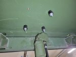
Remove bolts holding wiper motor to w/s frame.
Pull out as much as you can.
Remove nut holding linkage to the motor.
Turn wipers by hand to other side of w/s.
Put linkage back on motor with nut.
Put motor back on w/s frame.

The linkage only fits on motor in 2 positions, 180 degrees apart.
If you have tach on w/s frame, it will be easier to remove it.
You made it sound so easy, it was not but I guess it could have been much worse. The end result is it's done. Thanks for the instructions.

wipers.jpg
 

springer1981

Well-known member
844
1,150
93
Location
Maine
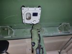
I changed the wipers because I was installing a dome light in front of the wiper motor. I changed the light switch so the open switch goes to the white light and the lock switch side goes to the blue light. I installed Rivnuts and rubber isolaters to mount the light.

domelight.jpg


domelight2.jpg
 

springer1981

Well-known member
844
1,150
93
Location
Maine
Approximately 5 weeks ago I made the comment that I just needed a simplistic valve to operate the rear steering cylinder rather than a much more expensive proportional type system. Then I explained a more complicated system. After explaining I got to thinking about it more and that was that. I determined a turret drive would give me a pretty complicated system fairly easily. The cost of a turret system is fairly expensive not knowing if I can even make it do what I want it to do. So rather than buy an expensive system or a bunch of known good working components I bought a bunch of junk and fixed it.

I thought I would include a breakdown of the cost to put together the turret system for my rear steering application.

60.00 2 inop joysticks
75.00 inop turret motor
66.00 untested BPMTU
80.00 joystick cable (rough condition)
64.00 shipping and tax for above

35.00 parts motor
10.00 motor bearing
10.00 motor bearing
14.00 motor seal
8.00 3 o-rings
26.00 power connector
37.00 motor connector
37.00 motor wire
35.00 power wire
12.00 gasket material
20.00 misc hardware and grease
35.00 shipping and tax for above

$624.00 Total Cost

The final results

 
Last edited:

springer1981

Well-known member
844
1,150
93
Location
Maine
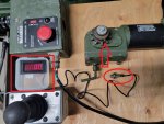
I have a digital hall effect sensing tach that I bought a few years ago for a project Lathe I built. I bought 2 at the time to have a spare but never used it. Today I mounted it in the case it came in and set it up. The Red Square is the tach. The Arrow points to the magnet and the Oval is the Hall sensor.

To calculate the gear reduction needed for the turret motor to turn the orbital valve I first need to know the Min and Max RPM of the turret drive system.

tach.jpg

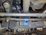
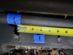
I also had to determine the amount of drag link movement during steering. So I marked the center of the drag link and the cross member then turned the wheels and measured it. About 2.75" movement in each direction.

Steering1.jpg

Steering.jpg
 
Last edited:

springer1981

Well-known member
844
1,150
93
Location
Maine
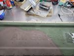
Started another project today, the tailgate! I mentioned previously that I would like to put on an "AM General" embossed tailgate. My truck is registered as an AM General pickup. Here's the story that goes with it.
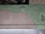
TG2.jpg

I found one on FB and the seller sent me pictures (he had a couple). It had a few problems but he had another one that he said was in better condition and sent more pictures. It did look better in the pictures and asked if it was all good, straight, no extra holes etc. He said yes and I bought it. Total cost with shipping was a little over $400. I didn't think that was unreasonable based on others I had seen. He packed it and shipped it quickly but it came from the other side of the country so it took over a week to get here.

I opened the box and as soon as I set it on the floor I could tell is was tweaked. I started checking it and it is twisted about 1.5 inches end to end. After looking closer I could see the hinge was bent a little and where the hinges attached were also bent in. Beside the twist there is also a bow in it. Basically this tailgate is unusable as it sits. If I tried to mount it, it would not close. I contacted the seller, albeit a little pissed off since it was so clearly damaged to me.

Ultimately he refunded $200 of the price and though I would likely have passed had I known about the damage I found that to be an acceptable compromise. This however leaves me needing to fix the tailgate if I am going to use it and that is what I chose to do.

The tailgate is basically made up of a few parts. There is the top, center section, 2 end fillers/caps and 2 hinges. The top has to come off first. One side has tapered rivets with aluminum body and steel mandrel, this is important to know for reassembly. The rivets mandrel breaks flush with the top of the taper and to remove them I found using a small punch and hammer to drive the mandrel out first then a 3/16 drill to pop the taper out the easiest way. Then a slightly larger punch to drive the rivet body through. In some instances I had to use a 1/8" drill to take the top 1/32" off the mandrel to punch it through.
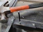
TG1.jpg

After I had all the rivets out of the top bar I used a large dead blow to get it off the center section. Then continued removing rivets down both side until the end fillers were removed. The hinges were next. They are Steel/Steel rivets, steel body and steel mandrel. I found the easiest way to remove them was to cut the top off first and then the mandrel could be punched out. Then drill the head until it popped off and punch the rest out.
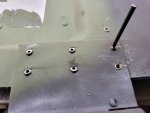
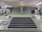
TG3.jpg
 
Last edited:

springer1981

Well-known member
844
1,150
93
Location
Maine
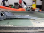
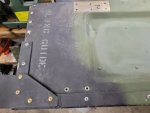
One of the hinges is bent and where both of them attach to the tailgate the tailgate is bent.

TG4.jpg

Here it is with the top removed. you can see the end fillers and the hinges above it.

TG5.jpg

After it was all disassembled I tried to capture the essence of the Twistedness. You can see I tried to capture the left side of the tailgate as squarely and flat as I could so it could be compared to the right side of the tailgate. It is twisted about 1.5" and there is a bow about a quarter of the way from the left side. With all the structure now removed, I'm hoping I can straighten it.

TG6.jpg
 

Maxjeep1

Well-known member
Steel Soldiers Supporter
1,338
1,918
113
Location
Las Vegas Nevada
I would take the twist out while it was on the truck. I would hook the chain on the good side and leave it off the other side and put some ass on it until it comes out. Probably set it on 2x4 while on the ground to get the center bow out. I can’t tell how bad it is from the pics
 

springer1981

Well-known member
844
1,150
93
Location
Maine
I would take the twist out while it was on the truck. I would hook the chain on the good side and leave it off the other side and put some ass on it until it comes out. Probably set it on 2x4 while on the ground to get the center bow out. I can’t tell how bad it is from the pics
If all you wanted was for the tailgate to be close, that might have worked. One of the reasons I didn't do that is the hinge is bent and needs to be fixed. The hinge attaches to metal that is thinner and when you try to straighten the hinge it just bends the metal it is attached to rather than straightening. Another reason is I want it to look good and correct as if it was never damaged when I am done. The only way to do that is to take it apart and do it right.
 
Last edited:

Maxjeep1

Well-known member
Steel Soldiers Supporter
1,338
1,918
113
Location
Las Vegas Nevada
If all you wanted was for the tailgate to close, that might have worked. One of the reasons I didn't do that is the hinge is bent and needs to be fixed. The hinge attaches to metal that is thinner and when you try to straighten the hinge it just bends the metal it is attached to rather than straightening. Another reason is I want it to look good and correct as if it was never damaged when I am done. The only way to do that is to take it apart and do it right.
I would imagine that it got the twist from the same way I described to get rid of it. How else would it get twisted? I have seen new hinges for sale on one of the big suppliers Mac, AM General, Hummer parts guy. Taking it apart isn’t a bad way to fix it and it will probably turn out better. Probably should’ve taken the twist out before you took it apart
 

springer1981

Well-known member
844
1,150
93
Location
Maine
I would imagine that it got the twist from the same way I described to get rid of it. How else would it get twisted? I have seen new hinges for sale on one of the big suppliers Mac, AM General, Hummer parts guy. Taking it apart isn’t a bad way to fix it and it will probably turn out better. Probably should’ve taken the twist out before you took it apart
I took it apart because it is too rigid to untwist while assembled. I think I can fix it much easier apart. I believe it is twisted due to an accident in the rear of the vehicle but I am not sure.
 
  • Like
Reactions: OBX

springer1981

Well-known member
844
1,150
93
Location
Maine
I would take the twist out while it was on the truck. I would hook the chain on the good side and leave it off the other side and put some ass on it until it comes out. Probably set it on 2x4 while on the ground to get the center bow out. I can’t tell how bad it is from the pics
Ive see them bow from the hitch. And twist when only one chain is hooked and too much weight put on open gate.
Maxjeep1, Ok, Now I understand what you meant about the chain.

Action, The bow is not where the hitch is, it's about a quarter of the way from the left side. It's also on the side with the bent hinge. It's not a gradual bow either, almost a kink or a bend. Again, I think it was in an accident but maybe it just had a very hard life.

Either way, it is apart now and will be fixed (I think).
 

springer1981

Well-known member
844
1,150
93
Location
Maine
Tailgate update:
After taking the tailgate apart I was able to mostly untwist it. I would have needed a press to get the last of it out. I think it will be fine. I reassembled it and it's ready for paint. I was also able to straighten the hinge out with a large fine tuning tool. Now I am waiting on the right rivets to put the hinges back.

tailgate.jpg
 

springer1981

Well-known member
844
1,150
93
Location
Maine
In another thread I mentioned an option to add a keyed ignition and steering column lock. I don't like the key/lock replacement for the stock ignition switch and have been wanting something different. I decided to buy the one I suggested to see if I could make it work. One of the requirements for me is that it has to look and function like it belongs, like it could have come that way. I think when this is mounted and painted it will look like it came that way.

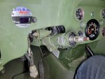
First I removed the directional switch mount to see where a good mounting location would be on the steering column.

Lock1.jpg

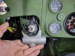
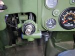
The mounting location also needs to clear the gauge panel when you turn the key. In this picture it is closer than it appears. In my case I shortened the steering column 2" so everything is a tight fit. I lined it up and marked it with a sharpie. If the steering column was stock length it would fit with plenty of room to spare.

Lock2.jpg

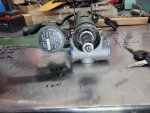
Then I pulled the steering column and set it up on the bench to figure out how to mount the directional switch after the ignition switch and lock is mounted. This ignition switch/lock was missing the top clamp and needs to be returned. I have one on the way with the top clamp but this works fine for measurements. Next I have to take the steering column apart and machine the shaft for the locking lug.

Lock3.jpg
 

springer1981

Well-known member
844
1,150
93
Location
Maine
Last night I brought the steering column and ignition to my machine shop to fit them together. To be honest, it's a match made in heaven! That doesn't make it easy but it's not hard just time consuming and requires the right tools.

In an earlier modification I shortened the steering column by 2". This complicated my installation but in stock form there is more clearance for the switch and it would be easier to do in general but just as much work to install. Here is where I started shortening the column https://www.steelsoldiers.com/threads/my-new-1992-m998-avenger.184818/post-2342450

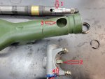
Number 1 is a slot that needs to be milled in the steering shaft for the lock lug (number 2). Number 3 is the locating hole for the switch and matches number 4 aligning the lock lug with the slot in number 1. The diameter of the switch housing matches the diameter of the steering column. More on the assembly still to come, I have to make the directional mount next.

Lock4.jpg

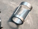
When I shortened the column I had to make a tool to take the column apart. It is an absolute requirement to disassemble the column. Here is a picture of it. When I made it I thought it would be a one time use tool, glad I kept it!

tool.jpg
 

springer1981

Well-known member
844
1,150
93
Location
Maine
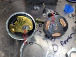
In my quest to have a stock like locking steering column with ignition switch I decided to inspect the chinese key switch that some previous owner had installed. Also I like to cut stuff open whether I need to or not.

The contacts are well made and solid copper but unfortunately the wiper contact is thin brass. You can see the significant arc burn marks in the metal. The burnt contacts are the ones that drive the starter. The brass contact is burn all the way through.

ignswitch.jpg
 

springer1981

Well-known member
844
1,150
93
Location
Maine
Today I mounted the ignition switch after painting it to match. I also wired it up and it works perfectly. I did take the ignition switch apart to example the construction of the contacts and assembly in general. At some point I will probably make a more heavy duty switch but for now i think it will work fine.

switch1.jpg

Top clamp in place. The tab on the left side of the top clamp is going to be used to mount the directional switch later. I have to make a mount for it. I will probably replace the phillips screws with some tamper resistant screws on final assembly.

switch2.jpg

Here it is with the steering wheel in place

switch3.jpg

On my truck the steering column is shortened 2" so the key switch is a tight fit but still plenty of room to operate the switch.

switch4.jpg
 

springer1981

Well-known member
844
1,150
93
Location
Maine
Once I get the directional mount bracket figured out and maybe a switch upgrade I might offer this service and see if anyone is interested in the conversion.

I still have a stock steering column and parts on the way to work on that conversion. Do you think this is something people would like, please post and let me know.
 
Last edited:
Top
AdBlock Detected

We get it, advertisements are annoying!

Sure, ad-blocking software does a great job at blocking ads, but it also blocks useful features of our website like our supporting vendors. Their ads help keep Steel Soldiers going. Please consider disabling your ad blockers for the site. Thanks!

I've Disabled AdBlock
No Thanks