• Steel Soldiers now has a few new forums, read more about it at: New Munitions Forums!

  • Microsoft MSN, Live, Hotmail, Outlook email users may not be receiving emails. We are working to resolve this issue. Please add support@steelsoldiers.com to your trusted contacts.

My second MEP-831A

AfghanVeteran2010

Active member
Steel Soldiers Supporter
293
29
28
Location
Odessa/Texas
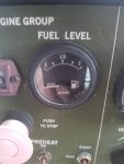
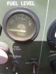
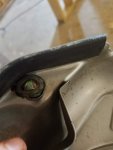
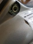
They probably had other issues with it, the military will get them another one if it cost so much to fix the broken one. I don't remember the percent. I know this one has a electrical problems with the fuel gauge it has a shorting out point to a terminal screw.

20171106_134155.jpg20171106_134203.jpg
 

AfghanVeteran2010

Active member
Steel Soldiers Supporter
293
29
28
Location
Odessa/Texas
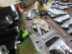
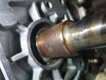
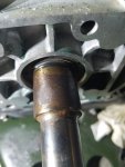
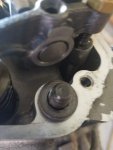
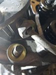
Look what I found, after removing it and putting the cover back on. Filled it with oil and gave it a few pulls and OIL pressure. I might have to replace the seal if I tore it. Going to order a oil pump O ring and a gasket for the cover, don't think there are supposed to be reused.

20171111_144709.jpg20171111_155003.jpg20171111_155006.jpg

https://youtu.be/k8rsLjeSvvg
 

AfghanVeteran2010

Active member
Steel Soldiers Supporter
293
29
28
Location
Odessa/Texas
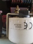
Normally, the meter doesn't go back that far. Non standard meter?
Looked up NSN: 6680-00-933-3600

Beede is not on cross reference list.

Beede info
MEP802A-MEP803A-MEP80XA/B Fuel Gauge – Special Scale Meter 6625-01-366-0193 Beede 945331


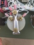
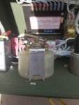
I am probably going to trim off some of that screw. If I ever get this set to work to spec ill fix fuel level problem requiring parts from the web.
New Set
20171111_124029.jpg20171111_124308.jpg

Older Reference Set
20171111_124236.jpg20171111_124239.jpg20171111_124241.jpg
 

Guyfang

Moderator
Staff member
Moderator
17,029
24,888
113
Location
Burgkunstadt, Germany
There are approx 35 different part numbers and 14 different NSNs for this meter. The NSN 6625-01-366-0193 or the part number 945331 is not one of them.

I won't say the Beede meter won't work. I guess it will. But it is NOT used in this application. I guess the old adage, If it works, don't screw with it will apply.
 

Guyfang

Moderator
Staff member
Moderator
17,029
24,888
113
Location
Burgkunstadt, Germany
There is no HEL* deep enough, or hot enough, for who ever did that. And its happened to me also. There is NO WAY that could have happened other then someone doing it on purpose.
 

AfghanVeteran2010

Active member
Steel Soldiers Supporter
293
29
28
Location
Odessa/Texas
I'm not too mad about it, I learned something from it. Before this I never took an engine apart or even had an understanding of what happens in a small diesel.
 

DieselAddict

Well-known member
Steel Soldiers Supporter
2,556
2,156
113
Location
Efland, NC
On the positive side this is a pretty simple engine to work on and the parts are affordable when you have to replace something.
 

AfghanVeteran2010

Active member
Steel Soldiers Supporter
293
29
28
Location
Odessa/Texas
Replace the oil seal, I was missing the head washers that go under the rocker cover. Had some washer on hand the were a little to wide, so I swapped out the ones that are not under cover. Also replace the flywheel cover vibration absorbers they turned into old bubble gum. Also replaced the seal that goes around the cover too. I did run into a issue today, I can not for the life of me to get the rotor to meet clearance requirements. I tried five times to reinstall the rotor no luck with TM procedures. Going to get a Mylar piece of plastic like a cutting board and use it as a spacer while installing. Dewie38 suggested this in another post to use this method.
20180423_120136.jpg20180423_120143.jpg20180423_124707.jpg20180423_124715.jpg20180423_125323.jpg20180423_125402.jpg
 
Last edited:

DieselAddict

Well-known member
Steel Soldiers Supporter
2,556
2,156
113
Location
Efland, NC
Do you have any file folders? That will also work. They should be a little thinner than the thin plastic cutting boards.
 

AfghanVeteran2010

Active member
Steel Soldiers Supporter
293
29
28
Location
Odessa/Texas
The cutting boards measured .030" I tried them, way too think to even let the rotor fit in stator. I took the screw our of my both of my feeler gauges to used them as a space on the side that was too close before. If i hit the rotor with a rubber mallet it will seat its self, once i try to remove the space its takes quit a bit to remove them. Then its too close at other points on the same side, around .008"-.006". I can pull the cord and hold down the decompress lever I don't hear rubbing. Going to take dav5 offer up on those shims.

20180424_184711.jpg
 

AfghanVeteran2010

Active member
Steel Soldiers Supporter
293
29
28
Location
Odessa/Texas
And were up and running. Seems Fuel gauge now does not work after it shorting out and the plugs GFI is faulty. Going to have to troubleshoot the fuel gauge in a bit. I can care less about the plug ATM.

https://youtu.be/y5bsDREkJ5A


Also a big thanks to Dav5 for sending the shim stock.
 
Last edited:

AfghanVeteran2010

Active member
Steel Soldiers Supporter
293
29
28
Location
Odessa/Texas
NO READING ON KILOWATT (LOAD)METER (M2) WHEN LOAD IS APPLIED

Disconnect P17 from A8 and perform the following tests:
a. Set multimeter to read resistance. Multimeter should read 100 ohms at LOAD meter terminals on back of meter. If reading is less than 100 ohms,remove and replace LOAD meter (WP 0036).
b. If 100 ohms is present at LOAD meter,check wiring between LOAD meter and P17. Remove and replace damaged wiring, as required.


Turn out that even if the meter reads around 100 ohms, that doesn't mean the meter is any good. Spent a better part of a hour looking at the schematics and wire numbers to see where this goes. The load meter goes to the Frequency Converter all the wring checked out, was starting to think that the Frequency Converter was messed up in some way.

So I tried changing the meter and it worked like it should.

I think the TM needs a change to read the load wires from the Frequency Converter

If 100 Ohms is present and continuity from wires 122B18, 121B18 to P17 is good. Disconnect wire 122B18 (+) from load meter, connect multimeters red lead to wire it and the other lead wire to the 121B18. Set multimeter to (DC). Start gen set and apply various loads to set while checking voltage on multimeter for change.
If voltage changes with load, remove and replace LOAD meter (WP 0036).

Something like this need to check if DC would be correct setting, I'm fairly sure that the voltage reading should be the same at 1KW load between different 831's. It just gets its reading from a Current Transducer inside the Frequency Converter from what I understand.
 
Top
AdBlock Detected

We get it, advertisements are annoying!

Sure, ad-blocking software does a great job at blocking ads, but it also blocks useful features of our website like our supporting vendors. Their ads help keep Steel Soldiers going. Please consider disabling your ad blockers for the site. Thanks!

I've Disabled AdBlock
No Thanks