40Amps is
way too low for the glow plugs. Each plug will draw between 10-20 amps depending on the plug model (80-160Amps total).
Yes, I will always advocate for putting the glow system back to stock - you can do the resistor bypass, but the rest of the glow system should be up to snuff IMHO. I know you want to use the block heater all the time, but there will likely be an occasion where you need to stop and start the truck away from wall-power. If it sits for an hour or more, you might need the glow plugs to get it to run easily.
Remember that the GM 6.2 diesel is a pre-combustion chamber type engine, the glow plugs heat that little "pre-cup" for each cylinder so the fuel burns better when the rest of the block is cool. From the "-20" TM:
"...
(c) ignition of fuel occurs because of heat developed in combustion
prechamber. As a result, no spark plugs or high-voltage ignition system is
required. For cold starts, glow plugs heat up combustion prechamber.
..."
So the most "bang for your buck" comes from getting those pre-cups warm before cranking (exactly what the glow plugs are there for).
There are some basic things that happen when the factory wiring is working correctly:
- When the coolant is cooler than 100°F, the cold advance and high idle solenoid is triggered (makes it easier to start, gets it warmer faster)
- When the coolant is cooler than 125°F, the glow plugs are run (pre-heats the combustion chambers so they will burn fuel when the engine is cranked)
When everything is working correctly, this will happen "automagically" without plugging into a wall outlet. The GP relay is there because the relay can control a higher current load than your average toggle switch (usually a max of 20Amps). Think of it like the solenoid on a starter - the little switch in the steering column can probably handle 10Amps, which is enough to run a relay under the dash which can handle 80Amps, which is enough to handle the solenoid on the starter which can handle 1500Amps... Like successively bigger dominoes.
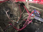
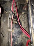
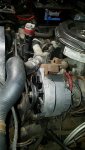
From the factory there was a fusible link that protected the fat wire coming from the battery to the glow plug relay, from the glow plug relay to the plugs there was a split of orange wire about half the gauge of the supply, that sent power to each bank of the block (left/right), from there it split off to four individual wires to supply the individual plugs. I do not recall if they used fusible links downstream of the GP relay (but I hope they did...). For your setup, you want power coming from the battery to go through a fuse, then to the GP relay, to the to the plugs just like the factory did. A toggle switch (if that's how you're doing it) should ground one side of the GP relay's fully isolated coil to the chassis, the other leg of the coil should get fused power from the ignition circuit - this way your plugs can't be run without the key in the "On" position (keeps kids and other people from burning out your plugs). If you keep the GP-card, the same toggle switch can be used for manual override, as the GP card should only be grounding the lower leg of the coil to chassis ground when it wants glow.
One thing to consider - a block heater is going to be >500Watts and the most common block plug type is not self regulating, meaning if you leave it on all the time (like the Coast Guard or a Fire Department might), that's the equivalent of a shop light (or two or three) running non-stop. The power bill for that would be ridiculous...
 The other thing I worry about with unattended block heaters is fire...

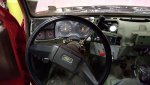
") Looks like a fun project
Looks like a fun project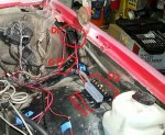
 . Here's why I worry, and I'm hoping you continue your interest in this: