• Steel Soldiers now has a few new forums, read more about it at: New Munitions Forums!

  • Microsoft MSN, Live, Hotmail, Outlook email users may not be receiving emails. We are working to resolve this issue. Please add support@steelsoldiers.com to your trusted contacts.

Niehoff N3030 Regulator/ M1078/ doesn't have flashing light capacity

Reworked LMTV

Expedition Campers Limited, LLC
Supporting Vendor
1,504
1,169
113
Location
TN
Delco 28SI 24V 110 Amp 8600469 8600423 Quad Mount 8762

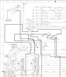
I got it from eBay. It's technically only 110a but test sheet goes to 130. Mine is the generic knockoff I believe. There's a price bump if you get the non knockoff version. Probably around $300. The OEM style unit has "Delco" name stamped into the black plastic cover on the back. I've seen this labeled with the Cummins label for as much $550. I've circled the cat # on the spec sheet in the 2nd photo.

this bolts into the 4-1/4"set of holes horizontally whereas the neihoff bracket uses the outer holes. Pulley lines up exactly.

this unit has remote voltage sense so I put that in too, fused line back to the batt +. I'm also driving a tach from the ac terminal.

with @Ronmar help, I was able to use the i terminal to drive the "charging system" warning light on the dash. Just needed a diode in line.

I'm at 28.00 volts while driving normally on my DMM meter. No change really unless the AIH is on. In March I tested the amperage and it was pulling 115 after a startup. That AIH is a hog.
View attachment 926189View attachment 926190View attachment 926191View attachment 926192
Thank you. Very helpful!
 

Lugnuts

Active member
Steel Soldiers Supporter
309
234
43
Location
Myakka City, FL
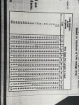
So I have started the Alternator Project and am installing 24vdc 110 Amp Alternator and I gained access to my Power Panel. I am going to install two Orion Victron's to this unit, one will be operating my 12vdc running works and one will be wired for my Emergency Side, lights and communications. Now I see that on the Power Panel my 24vdc wire is guessed to be a 4 gauge?, and I am wondering if that one wire will handle the load of both Victrons if they were maxed out, OR would I be better to take the 12vdc wire on X2 and make it another 24vdc wire by disconnecting it from 12vdc on both ends and connecting is 24vdc on both ends? I am going to throw in a wire gauge/ amp load chart that I have had for years. It seems they are disappearing in lieu of figure it out yourselves type apps. It seems by the chart that I would be alright but being safe is always a good thing. Input please. and thank you
 

Attachments

GeneralDisorder

Well-known member
Steel Soldiers Supporter
1,998
5,126
113
Location
Portland, OR
4 AWG is roughly good for 75 amps. Could be higher or lower depending on rating but being mil spec it's probably 90C rated copper which is actually like 95 amp rated.

If you want to be safe then re-purpose the 12v lead to the panel for one of the Victrons and just hook it to 24v instead.
 

Ronmar

Well-known member
3,785
7,352
113
Location
Port angeles wa
So I have started the Alternator Project and am installing 24vdc 110 Amp Alternator and I gained access to my Power Panel. I am going to install two Orion Victron's to this unit, one will be operating my 12vdc running works and one will be wired for my Emergency Side, lights and communications. Now I see that on the Power Panel my 24vdc wire is guessed to be a 4 gauge?, and I am wondering if that one wire will handle the load of both Victrons if they were maxed out, OR would I be better to take the 12vdc wire on X2 and make it another 24vdc wire by disconnecting it from 12vdc on both ends and connecting is 24vdc on both ends? I am going to throw in a wire gauge/ amp load chart that I have had for years. It seems they are disappearing in lieu of figure it out yourselves type apps. It seems by the chart that I would be alright but being safe is always a good thing. Input please. and thank you
70A @ 12v = 35A @24v. Both together will pull ~70A@24 if they are ever maxxed-out. using the wire calc and 90A(the truck only uses ~10 or so @24v) 6AWG would be good for 20' at 90A load, so 4AWG should be more than fine for 24v up to the cab feeding 90A.

here is a link to the wire gauge calc.


hike

—realizing each day
Steel Soldiers Supporter
527
832
93
Location
Texas Hill Country
70A @ 12v = 35A @24v. Both together will pull ~70A@24 if they are ever maxxed-out. using the wire calc and 90A(the truck only uses ~10 or so @24v) 6AWG would be good for 20' at 90A load, so 4AWG should be more than fine for 24v up to the cab feeding 90A.

here is a link to the wire gauge calc.

I would plan out your loads. The first Victron running the truck will likely never approach capacity; the second Victron all depends upon what you are adding–
 

MatthewWBailey

Thanks for this site. My truck runs great now!
Steel Soldiers Supporter
794
1,446
93
Location
Mesa Colorado
So I have started the Alternator Project and am installing 24vdc 110 Amp Alternator and I gained access to my Power Panel. I am going to install two Orion Victron's to this unit, one will be operating my 12vdc running works and one will be wired for my Emergency Side, lights and communications. Now I see that on the Power Panel my 24vdc wire is guessed to be a 4 gauge?, and I am wondering if that one wire will handle the load of both Victrons if they were maxed out, OR would I be better to take the 12vdc wire on X2 and make it another 24vdc wire by disconnecting it from 12vdc on both ends and connecting is 24vdc on both ends? I am going to throw in a wire gauge/ amp load chart that I have had for years. It seems they are disappearing in lieu of figure it out yourselves type apps. It seems by the chart that I would be alright but being safe is always a good thing. Input please. and thank you
One ampacity chart is as good as any. Just use "free air" ratings and not "in conduit" ratings.

Here's what I did. I use x3 in the PDP to power victrons (two 20a units) to power x2, with the existing 12v lead still there connected to a 3rd 12v only battery so I have light power when ignition is off. If you have high loads on your 2nd victron, just repurpose the 12v lead as another 24v from the batt as @GeneralDisorder said. As always, electrical design STARTS with a wattage accounting of planned loads, not the size of the power supply. Overkill is common when adding up amperages. Use total watts, then add demand factors (not everything runs at once) before committing to a PS and wire size. I put two 20a victrons to run the cab and was quite disappointed as the 12v cab bus barely draws 12.5amps if I can manage to turn everything on.
552FFAA2-45B6-451E-B428-F7A34819EEFE.jpegD7DAA5C8-2730-4C5B-99E7-6EFDC77BD913.jpeg
 

MatthewWBailey

Thanks for this site. My truck runs great now!
Steel Soldiers Supporter
794
1,446
93
Location
Mesa Colorado
With the LBCD and remote disconnects removed wouldn't it be better to have the alternator connected to the battery side of the manual disconnect rather than feeding directly to X1?
So the idea was to have a way to still safely work on the ALT after removing remote disconnects. If the truck is running and someone operates the manual disco, yes, that's not good. But when is that going to happen? I pity the fool! If it's a worry, I could always put a yellow lock in the "on" position. This way, I still have the factory safety feature of knowing I won't short the 24+ lead at the ALT once the disco is operated. The same could be said of the starter (hence the RTV on starter terminals safety workaround posted elsewhere). Seems to be a net benefit to keep the manual disco in the ALT circuit.

I hold these truths to be self evident.
 
Last edited:

hike

—realizing each day
Steel Soldiers Supporter
527
832
93
Location
Texas Hill Country
We disconnect batteries when working on starters and alternators, believing the greater risk is to electrical system if the disconnect is flipped on a whim. I'd rather buy an alternator than an ECM—
 

MatthewWBailey

Thanks for this site. My truck runs great now!
Steel Soldiers Supporter
794
1,446
93
Location
Mesa Colorado
We disconnect batteries when working on starters and alternators, believing the greater risk is to electrical system if the disconnect is flipped on a whim. I'd rather buy an alternator than an ECM—
I hear ya. The disco is equipped with a locking hasp for that reason. You can lock it on or off.
 

GeneralDisorder

Well-known member
Steel Soldiers Supporter
1,998
5,126
113
Location
Portland, OR
The manual switch doesn't function any different than the disconnect relay. At least in the stock configuration the LBCD is designed to allow the batteries to be disconnected from the charging circuit and *not* cause a spike that nukes the electronics from orbit.

Of course if you have deleted the LBCD....... probably should also delete the manual disconnect if you think someone may run up and flip it while you are at an intersection.
 

Lugnuts

Active member
Steel Soldiers Supporter
309
234
43
Location
Myakka City, FL
One ampacity chart is as good as any. Just use "free air" ratings and not "in conduit" ratings.

Here's what I did. I use x3 in the PDP to power victrons (two 20a units) to power x2, with the existing 12v lead still there connected to a 3rd 12v only battery so I have light power when ignition is off. If you have high loads on your 2nd victron, just repurpose the 12v lead as another 24v from the batt as @GeneralDisorder said. As always, electrical design STARTS with a wattage accounting of planned loads, not the size of the power supply. Overkill is common when adding up amperages. Use total watts, then add demand factors (not everything runs at once) before committing to a PS and wire size. I put two 20a victrons to run the cab and was quite disappointed as the 12v cab bus barely draws 12.5amps if I can manage to turn everything on.
View attachment 927960View attachment 927961
Please instruct me...... What is in conduit rating versus free air ratings?? I mean I know what the name implies but how does that effect the amp ratings on small wiring such as what we are using? Thank you?
The other thing I am dealing with is the unknown future load, incandescent or LED, what new radio or charger are we going to install. My Watts load is unknown so I need to supply for it ahead of time. I failed to mention that this is being used as a High Water Truck in Fire Service.
 

Ronmar

Well-known member
3,785
7,352
113
Location
Port angeles wa
Please instruct me...... What is in conduit rating versus free air ratings?? I mean I know what the name implies but how does that effect the amp ratings on small wiring such as what we are using? Thank you?
The other thing I am dealing with is the unknown future load, incandescent or LED, what new radio or charger are we going to install. My Watts load is unknown so I need to supply for it ahead of time. I failed to mention that this is being used as a High Water Truck in Fire Service.
It has to do with heat dissipation. All wires have resistance and will creat heat with current flow. If it cannot dissipate that heat it will damage/melt the cable insulation. That is one reason for those amp to cable gauge calculators, acceptable heat management and acceptable voltage drop.

I Picked up an extension cord on a reel at work a few months ago off one of the vehicles. Started to unreel it to use it and got about half way and it stopped unreeling. The inner windings, about 50’ worth, were melted together and fused, because someone had not fully unwound the extension cord and pulled a large electrical load thru it. The inner coils on the spool melted together… Note to everyone, always fully unwind/uncoil extension cords…

4AWG to the cab is I think good to 160A up to a length of 20’(longer than your run), so you should be fine with that cable that is mostly run out in free air…
 

MatthewWBailey

Thanks for this site. My truck runs great now!
Steel Soldiers Supporter
794
1,446
93
Location
Mesa Colorado
The manual switch doesn't function any different than the disconnect relay. At least in the stock configuration the LBCD is designed to allow the batteries to be disconnected from the charging circuit and *not* cause a spike that nukes the electronics from orbit.

Of course if you have deleted the LBCD....... probably should also delete the manual disconnect if you think someone may run up and flip it while you are at an intersection.
I actually wish for that😂. Gives me a chance to practice my Greco Roman wrestling😇. It's easy to lock it up or even move it to the inside of the cabinet with a lock so it's only a maintenance device. I guess I'll have to do it to keep everyone happy🙄
 
Last edited:

MatthewWBailey

Thanks for this site. My truck runs great now!
Steel Soldiers Supporter
794
1,446
93
Location
Mesa Colorado
Please instruct me...... What is in conduit rating versus free air ratings?? I mean I know what the name implies but how does that effect the amp ratings on small wiring such as what we are using? Thank you?
The other thing I am dealing with is the unknown future load, incandescent or LED, what new radio or charger are we going to install. My Watts load is unknown so I need to supply for it ahead of time. I failed to mention that this is being used as a High Water Truck in Fire Service.
What @Ronmar said👆👆👆. Here's a generic comparison of 4awg. 105 amps fee air before the rating of the insulation will be exceeded (I chose 60C conservatively). But Only 70 amps allowable in conduit, a cable assembly (Ronmars example) or buried in dirt. It doesn't matter what the voltage is. Heat is measured by the formula i^2*R which equals watts. So when you double the amps of a circuit, the heat generated is QUADroupled! In vehicles, some wires should use the "cable assembly" rating (bundles) and others can use the free air rating, like the big individual power feeds just running openly thru the compartment.

For load estimation, you're going to have to choose something, even if it's a SWAG. LED will drop the light load by 5x at least over the old incandescent. You can pick a radio, camera system, PA system, extra light bars etc like @kendelrio 's truck etc from the internet and just use those rough numbers.


D88E6CA5-0231-439F-A9D6-C671B8025E98.png88A9803B-2EDF-462B-9582-99EE6C9ABEDF.pngAD7387FD-6B47-452E-8568-FBD120FFF916.png90111906-8DC3-4B5C-914C-DB294BBF3ECD.png
 

Lugnuts

Active member
Steel Soldiers Supporter
309
234
43
Location
Myakka City, FL
The conversion is going great! And I plan on giving more information when I am done. I encountered another problem and looking for a remedy, I figured and proved that as soon as I bump the starter button, the starter lockout relay does its job. My 24 VDC alternator is a one wire alternator and it seemingly raises the voltage enough to kick my starter out. Now right now my remedy is to remove the K24 relay and jump the wire from 30 position to 87. It now stays engaged but I figure it will still engage even though the engine is running. So I am looking for a way to delay. Any suggestions please. Thank you.
 

Lugnuts

Active member
Steel Soldiers Supporter
309
234
43
Location
Myakka City, FL
I finished my rewire and am quite pleased. Thank y'all for the assistance.
My problem with the starter lockout relay is only going to be remedied if I find a way to delay my alternator from starting so soon. I have seen mention on the internet that there are one wire alternators that have a delay but I haven't found that yet.
The other problem I have encountered in that of having a Battery Hot 12vdc. Now I could run a line from the battery to the area or to me a cleaner way would be to have a small convertor for just that. It would be on all the time. You that have Live-In accommodations must have a battery hot 12vdc side and I am wondering what you do for that??? Would love the input.
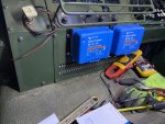
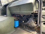
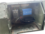
Last, just some photos to show the mounting of things. And I am modifying my floor kick panel to go back on there. Just haven't got a picture of it.

Thank you all!
 

Attachments

Top