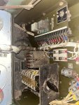
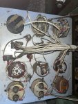
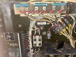
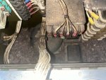
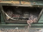
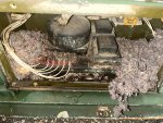
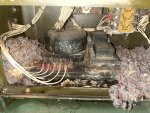
Normally when the AVR went bad on these sets, it was simply, No output at all. But you get 30-57 VAC. When running, will the ACV change slowly? Or quickly peg back and forth? While it is running, can you move the variable resistor back and forth, and have any influence on the ACV?Below is the variable resistor test procedure. simple and quick. Then you can exclude this from the possible problem list.
5. GENERATOR FAILS TO BUILD UP RATED VOLTAGE
Step 1. Check for loose, cut, broken, and worn wiring.
If connections are loose, tighten them. If wiring is damaged, repair it. Refer to paragraph 4-39
for repair instructions.
Step 2. Check for a broken or cracked voltage selector switch.
Check for damaged wiring.
If the voltage selector switch is damaged or defective, refer to paragraph 4-37 for removal and
installation instructions.
Step 3. Inspect the variable resistor for cracks, corrosion, loose connections and other damage. Test the
variable resistor as follows:
a. Stop the generator set and disconnect terminal 26 of the voltage regulator terminal board.
b. With a multimeter, check resistance across the variable resistor terminals by varying the
resistor from full counterclockwise to full clockwise position. This reading should move smoothly
from 0 to 750 ohms ± 10% as the variable resistor is rotated to the full clockwise position.
NOTE
On sets manufactured prior to 1968, this reading will be 0 to 250 ohms ± 10%.
Replace the variable resistor (para 4-16) if the reading is not within specifications.
Step 4. Check the voltage regulator for loose wires, corrosion, metal to metal contact, or incorrect wiring.
6. VOLTMETER READING TOO HIGH OR TOO LOW
Step 1. Check for a broken or cracked voltage adjusting rheostat switch. Inspect for broken wiring or
loose connections around the switch.
If voltage adjusting rheostat switch is damaged or defective, refer to paragraph 4-38 for
removal and installation instructions.
Step 2. Check for broken or cracked voltmeter. Inspect for broken wiring or loose connections. Test
voltmeter by connecting an additional voltmeter to load terminals of generator set and taking
comparative readings to establish validity of generator set voltmeter.
If voltmeter is damaged or defective, refer to paragraph 4-33 for removal and installation
instructions.
In the TM 5-6115-332-14, page 5-2 starts the DS troubleshooting. This is where you are going to find your solution I think. I wont post it here, as its long.
This is also something to check. Often when someone removed the wires, they did not hook the AVR back up as stated on the AVR data plate.
View attachment 937073


