• Steel Soldiers now has a few new forums, read more about it at: New Munitions Forums!

  • Microsoft MSN, Live, Hotmail, Outlook email users may not be receiving emails. We are working to resolve this issue. Please add support@steelsoldiers.com to your trusted contacts.

Picked up 6 MEP-802A gensets and will be documenting making them all runners here

pclausen

Well-known member
Steel Soldiers Supporter
452
281
63
Location
Afton, VA
Its making power!

I was getting AC voltage at the at the input to A/C interrupt, but nothing at the output. Turns out you have to push the A/C interrupt toggle switch to close momentarily begin making power... aua

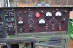
So while it was making power, neither the voltmeter nor the load meter were working. I swapped out the voltmeter but it still didn't show anything. I decided to worry about the gauges later and moved the unit outside and connected it to my dummy load:

MEP802-11-28-2015-01.jpg
http://www.cstone.net/~dk/MEP802-11-28-2015-01.jpg

I started out with a 4500W load and my voltage was high as seen here:

MEP802-11-28-2015-02.jpg
http://www.cstone.net/~dk/MEP802-11-28-2015-02.jpg

So 262 volts into a heater element rated at 4500W @ 240 volt. I had the voltage pot turned all the way down, so I guess there is a secondary adjustment somewhere?

Here's a video of running with the 4500W load:

http://www.cstone.net/~dk/MEP802power1.mp4

So the gauges that work are the coolant temp, charging and hz. After running for 3 minutes or so, the generator dropped the load and the overload indicator was lit. No sure why since my load was only 4912W (4500 / 240 * 262).

So I switched to one of the 3500W elements, and it kicked out again after a few minutes.

I guess I need to figure out why the voltage is too high and go from there. Hopefully its all related.

Another video as the unit was cooling down. Coolant temp get up there a bit! Radio in the tractor is playing Steady as she goes. Hopefully that indicative of what this generator will be doing eventually. lol

http://www.cstone.net/~dk/MEP802power2.mp4
 

CT-Mike

New member
238
2
0
Location
CT
Your normal coolant temp should be just above the 180 degrees F mark on the gauge.

Good luck on what's causing your overvoltage.
 

pclausen

Well-known member
Steel Soldiers Supporter
452
281
63
Location
Afton, VA
Thanks, I think 180 is what it was sitting at (which is about 3/4 scale).

I printed out section 2-27 AC VOLTAGE REGULATOR section from the service manual. I'll go through those steps in the morning to see if I need to swap out the voltage regulator from one of the other units.

Looks like 2-27-2 o. has a misprint. It reads:

If steps h. j, I and n are as Indicated above, AC voltage regulator IS defective and must be replaced

Pretty sure it should read:

If steps h. j, I and n are NOT as Indicated above, AC voltage regulator IS defective and must be replaced

I forgot to mention that the generator shut down on me near the end. The Low Fuel fault light came on. So I know that float switch works and is connected correctly. Sure wish my old Ford tractor had such a sensor. It's a pain to bleed it when it runs out of fuel. :D
 
Last edited:

pclausen

Well-known member
Steel Soldiers Supporter
452
281
63
Location
Afton, VA
Thanks, that's excellent info!

Did you measure the exhaust temp by shooting infrared at the manifold wall directly in front of where the head dumps it for one of the cylinders?

Assuming I get the over voltage issue solved and can run a 4500 watt load all day with no issue, I'll try 7000 watt, which is 140%. That might be too much, but I only have 2 x 4500 and 2 x 3500 heater elements that I can switch in and out. If 140% trips is, I'll see about picking up a lower wattage element. They are pretty cheap.
 
Last edited:

CT-Mike

New member
238
2
0
Location
CT
Thanks, that's excellent info!

Did you measure the exhaust temp by shooting infrared at the manifold wall directly in front of where the head dumps it for one of the cylinders?

Assuming I get the over voltage issue solved and can run a 4500 watt load all day with no issue, I'll try 7000 watt, which is 140%. That might be too much, but I only have 2 x 4500 and 2 x 3500 heater elements that I can switch in and out. If 140% trips is, I'll see about picking up a lower wattage element. They are pretty cheap.
Just keep in mind that a pure resistive load such as your heater elements have a power factor (pf) of 1.0. Your percent output meter is calibrated for a pf of 0.8 and so the meter will indicate lower than actual output when at load. Best to use your clamp-amp meter to determine loading.
 

pclausen

Well-known member
Steel Soldiers Supporter
452
281
63
Location
Afton, VA
God point about the 0.8 pf. I'll be sure to bring down my clamp meter down.

I got the over voltage issue resolved. Just had to adjust the range down some on the regulator. Looks like someone else had been messing with it. The trim pot is real loose and was turned all the way down (counter clockwise) which actually makes the voltage range as high as it can go. I'd like to put a drop of something on it to make it stay put. Perhaps just dapping a little think paint on there will do the trick?

Also found out that the oil pressure gauge was bad, so I swapped in another one. I checked the fuel gauge and it worked fine, but the fuel sender is bad (reads open with ohm meter). I tried pulling it out, but doing so requires removing the front section again!$#$!#@ So I'll just live with it for now I think. I checked the sender in a 2nd tank, and it read open too, but the 3rd one was showing about 250 ohms, which is about right.

This afternoon I'll look into whatever the issue is with the volt and load meters. The service manual seems to skip the part about testing the volt meter for some reason. I'll search around to see if I can find the procedure elsewhere in the manual.
 

DieselAddict

Well-known member
Steel Soldiers Supporter
2,532
2,059
113
Location
Efland, NC
I use fingernail polish on the pots. Its easy to break free in the future if you need to make and adjustment.

Plus the sparkly purple looks fabulous! :D
 

pclausen

Well-known member
Steel Soldiers Supporter
452
281
63
Location
Afton, VA
Thanks. I'll hit the wife up for some. I'll see what colors she has. :D

So I searched through my pdf file for the service manual, and section 2-46-2 is missing. This is the AC Voltmeter troubleshooting section.

The pdf I'm looking at is TM 9-6115-641-24 and is dated September 1993. Does anyone have a version that contains section 2-46-2?

Thanks!
 

jamawieb

Well-known member
1,437
556
113
Location
Ripley/TN
I've got the manual I think you need but can't figure out how to attach it so I copy/pasted it below.
2-46 AC VOLTMETER (VOLTS AC).
2-46.1
a.
b.
c.
d.
2-46.2
a.
b.
c.
d.
e.
f.
g.
h.
i.
j.
2-46.3
a.
b.
c.
d.
e.
f.
2-46.4
a.
b.
c.
d.
e.
Shut down generator set.
Release control panel by turning two fasteners and lower control panel slowly.
Inspect AC voltmeter (VOLTS AC) for cracked lens, loose mounting, corrosion, and other damage.
Raise and secure control panel.
Testing.
Release control panel by turning two fasteners and lower control panel slowly.
Set multimeter for AC volts and connect to AC voltmeter (VOLTS AC) terminals.
Move AC voltage reconnection switch to 120/208, 3-phase position.
Start and operate generator set at rated voltage and frequency.
Move AM-VM transfer switch to L3-L1, 3-phase position. Observe and note indications on multimeter and AC
voltmeter (VOLTS AC). Indications on both should be equal, ± 9 volts.
Move AM-VM transfer switch to L3-L0, 3-phase position. Observe and note indications on multimeter and AC
voltmeter (VOLTS AC). Indications on both should be equal, ± 9 volts.
Shut down generator set.
Replace AC voltmeter (VOLTS AC) if indications are not as above.
Remove multimeter.
Raise and secure control panel.
Removal.
Shut down generator set.
Open left side engine access door and disconnect negative battery cable.
Release control panel by turning two fasteners and lower control panel slowly.
Tag and disconnect AC voltmeter (VOLTS AC) (37, FIGURE 2-14) electrical leads.
Remove screws (35) and nuts (36).
Remove AC voltmeter (VOLTS AC) (37) from control panel.
Insert AC voltmeter (VOLTS AC) (37, FIGURE 2-14) into control panel.
Install screws (35) and nuts (36).
Connect electrical leads and remove tags.
Raise and secure control panel.
Connect negative battery cable and close access door.
 

pclausen

Well-known member
Steel Soldiers Supporter
452
281
63
Location
Afton, VA
Thanks for that!

So I connected my DVM in parallel with the AC Voltmeter and nothing. I then switched to 3 phase and low and behold, it started working. So I figured it was the AM-VM switch that was being f lackey. So I worked it through it's settings a good 20 times and did the same with the phase selector switch. What do you know, that did the trick! Still need to work on the load meter, but I decided I was far enough along to go ahead and put some of the covers back on.

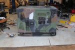
Front side all buttoned up and ready to be covered.

MEP802-11-29-2015-01.jpg
http://www.cstone.net/~dk/MEP802-11-29-2015-01.JPG

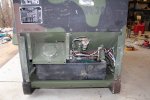
Alternator side. You can see the come-along I used to keep it from walking across the shop floor. :D

MEP802-11-29-2015-02.jpg
http://www.cstone.net/~dk/MEP802-11-29-2015-02.JPG

Figured I'd take it back outside and run it into a load again. Here's a video of it with a 3500W load:

http://www.cstone.net/~dk/MEP802Running04.MTS

It still trips the overload even though I'm now at 240V. I looked around for my current clamp but couldn't find it. Will need to look for it again to get to the bottom of whatever is causing it to trip.

MEP802-11-29-2015-03.jpg
http://www.cstone.net/~dk/MEP802-11-29-2015-03.JPG

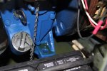
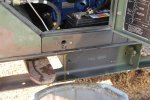
As I was getting ready to park the 802 back into the shop, I noticed an oil leak:

MEP802-11-29-2015-04.jpg
http://www.cstone.net/~dk/MEP802-11-29-2015-04.JPG

Looks like its the side cover that's leaking.

MEP802-11-29-2015-05.jpg
http://www.cstone.net/~dk/MEP802-11-29-2015-05.JPG

Well, at least that will be fairly easy to pull off. That will have to wait until next weekend.... Guess I'll use some silicone sealant on the gasket this time. I did check all the bolts and they are at the proper torque.

So one step forward and one step back...
 

Another Ahab

Well-known member
17,999
4,556
113
Location
Alexandria, VA
A small "gear-change" in the posts, but I was making a college tour with my daughter yesterday (University of Richmond):

- And walking by the biology labs ran across one VERY large temporary generator on a pad outside the building.

And it made me wonder about the longevity of the fuel (the fuel tank was built into the bottom of the unit).

Will that fuel be good indefinitely if properly treated and all?
 
Last edited:

DieselAddict

Well-known member
Steel Soldiers Supporter
2,532
2,059
113
Location
Efland, NC
Not indefinitely but it could last several years if conditioned properly. I would hope they have some type of maintenance runs that can give cause to bring in fresh fuel from time to time.

On our large diesel machines we would have a company come in every few years and run a camera around the tanks looking for problems. We also had fuel analysis quarterly to look for issues. Barring any length of power outage where the generators had to work hard we would turn the tanks over on maintenance runs every 18 months or so. If we were running online the tanks would last about 36hrs. That comes out to about 120-130gph to make almost 2Mw. In the 16 years I never saw anything on the fuel analysis the indicated a problem.

Here at home any diesel fuel I have in a solid sealed container kept in a cool dry location I wouldn't give a second thought for 36 months.
 

rustystud

Well-known member
9,280
2,987
113
Location
Woodinville, Washington
And it made me wonder about the longevity of the fuel (the fuel tank was built into the bottom of the unit).

Will that fuel be good indefinitely if properly treated and all?
Diesel fuel that has been properly treated can easily last up to 10 years in proper storage. I personally used fuel that was stored for over 5 years with no problems.
Now Kerosene that is sealed has been known to last for decades !
 

pclausen

Well-known member
Steel Soldiers Supporter
452
281
63
Location
Afton, VA
So what would one treat diesel fuel with and how would you go about mixing it if you had 100 gallons plus?

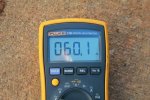
Spent some time with the 802 this morning. First I fired it up again to warm it up before draining the oil. Since I found my current clamp, I figured I'd do another load test while I was at it. I tested the accuracy of the Hz meter. My calibrated meter shows:

MEP802-12-5-2015-01.jpg


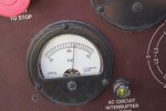
The one on the 802 shows:

MEP802-12-5-2015-02.jpg

So it's high by 1 Hz. Can I just turn that little slot below it to get it to show 60Hz?

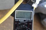
Here's what my current clamp is showing at 60Hz 240V into a 4000 heater element:

MEP802-12-5-2015-03.jpg

So 18.06 x 240 = 4,334 Watt. Generator still drops the load with an overload fault after a few minutes. So I take it there's an adjustment somewhere (hopefully) to increase the point at which it drops the load?

So with the oil nice and hot, I drained it:

MEP802-12-5-2015-04.jpg
http://www.cstone.net/~dk/MEP802-12-5-2015-04.JPG

I need to fix up some sort of extension tube to prevent the mess it made in the future. Oil was nice and clean though.

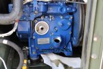
It was very easy to get the stuff out of the way to access the crankcase cover.

MEP802-12-5-2015-05.jpg
http://www.cstone.net/~dk/MEP802-12-5-2015-05.JPG

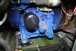
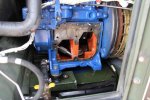
Cover removed:

MEP802-12-5-2015-06.jpg
http://www.cstone.net/~dk/MEP802-12-5-2015-06.JPG

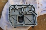
Inside of cover. Not really sure why it leaked...

MEP802-12-5-2015-07.jpg
http://www.cstone.net/~dk/MEP802-12-5-2015-07.JPG

I cleaned both surfaces with some break cleaner on a rag, stole another gasket from one of the other kits, applied a thin film of silicone to both sides, and re-installed the cover, torquing down the bolts to the proper spec in the proper sequence as per the service manual. Hopefully it won't leak this time. Need to pick up some more oil filters, so this is as far as I can go for now.
 
Last edited:

Korgoth1

New member
191
5
0
Location
radford, va
I have had good luck just keeping the tanks dry and clean, but power service makes a biocide that supposedly works as a preventative. Alot of that stuff is just snake oil... No.2 heating oil in my area comes treated to not gel, and hasn't on me down to -7 last year. And if there is no water in my tanks, I dont get the growies.

There is no adjustment like the 00x unit have, the new units use a bank of "burden resistors" the current transformer, AM/Vm switch, and short circuit relay to control the breaker.

Yes you can adjust the hz meter with the slotted plastic tab on the bottom.

If the cover leaks again, it may be warped, I have lapped the cylinder heads from my bike on a glass plate to get them true before.
 
Last edited:

pclausen

Well-known member
Steel Soldiers Supporter
452
281
63
Location
Afton, VA
My load meter isn't working yet, so I wonder if that is somehow related to the issue with the breaker tripping? The engine is having no issue handling the load. I just get a puff of black smoke right when I bring the load online, and then it goes about its business.

I'll see if I have some contact cleaner and I'll try spraying the AM/Vm switch and the phase select switch with it, and see if that gets the load meter going and resolves the issue. Moving both of those switches back and fourth is what got the volt meter going.

The "burden resistors" all appear to be in great condition on this unit. Some of the other 802 units I have appear to have had some work done in that area.
 

DieselAddict

Well-known member
Steel Soldiers Supporter
2,532
2,059
113
Location
Efland, NC
Your meter not reading could absolutely be related to the breaker tripping.

Have you exercised the reconnection switch in addition to the AM/VM switch? Move it fully left and right at least 10 times.

Have you popped the lid off and gone through all the terminals looking for loose things?
 
Top