• Steel Soldiers now has a few new forums, read more about it at: New Munitions Forums!

  • Microsoft MSN, Live, Hotmail, Outlook email users may not be receiving emails. We are working to resolve this issue. Please add support@steelsoldiers.com to your trusted contacts.

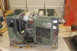
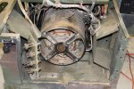
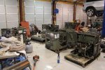
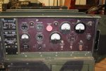
Picked up 6 MEP-802A gensets and will be documenting making them all runners here

jamawieb

Well-known member
1,437
556
113
Location
Ripley/TN
My load meter isn't working yet, so I wonder if that is somehow related to the issue with the breaker tripping? The engine is having no issue handling the load. I just get a puff of black smoke right when I bring the load online, and then it goes about its business.

I'll see if I have some contact cleaner and I'll try spraying the AM/Vm switch and the phase select switch with it, and see if that gets the load meter going and resolves the issue. Moving both of those switches back and fourth is what got the volt meter going.

The "burden resistors" all appear to be in great condition on this unit. Some of the other 802 units I have appear to have had some work done in that area.
I have the same issue with a 803a, drops load at 34 amps and my load meter is only reading 20%. That project is on the back burner right now since I have 003a with issues that I need to get resolved first. One thing on the 003a, the load meter was not working correctly and I sprayed the phase select switch (reconnection switch) with WD-40, then worked it between positions about 20 times and then the load meter started working correctly. It was very hard to move between positions (same as the 803a), and after 20 times of moving it, it moved freely. So I'm beating if I do the same thing to the 803a, everything will work correctly. From the wiring diagram, load sensing goes through the am/vm connector, burden resistors, and the phase selector switch.
 
Last edited:
Korgoth1

New member
191
5
0
Location
radford, va
Since the head was off, I figured I might as well go ahead and time the pumps and see if the shims were correct. The procedure is to find TDC on the fire stroke for each cylinder, then turn the crank backwards to a piston drop of just over 0.990", the rotate forward again to get to the 0.990" point. At this point you measure the depth from the top face of crankcase to top of fuel tappet cap. You then subtract the injector pump dimension which has a default value of 2.02".
This confuses me, the TM lists ".99in (2.519mm)" and 2.519 mm is not .99 in! It is closer to .099in!
So is it .99in piston drop or 2.519(.099in) piston drop?
 

pclausen

Well-known member
Steel Soldiers Supporter
452
281
63
Location
Afton, VA
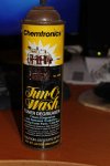
I found my trusty old can of Tun-O-Wash last night. It is almost full. I'll spray that stuff into all the openings I can find on both the AM/VM switch and phase selector switch and work them as you suggest. I think I did them both maybe 5 times or so already, so I'll be sure to do at least another 10 times each. :D

tunowash.jpg
 

pclausen

Well-known member
Steel Soldiers Supporter
452
281
63
Location
Afton, VA
This confuses me, the TM lists ".99in (2.519mm)" and 2.519 mm is not .99 in! It is closer to .099in!
So is it .99in piston drop or 2.519(.099in) piston drop?
I'm 99% certain (pardon the pun :D ) that its 0.99". I say this because I remember it being right at the edge of the range of my dial gauge's range of 1". I'll double check my notes if I can find them.
 

pclausen

Well-known member
Steel Soldiers Supporter
452
281
63
Location
Afton, VA
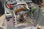
I sprayed the switches with the Ton-O-Wash and worked them end to end about 15 times. While I wait to pick it some more oil filters, I decided to move on to another unit. This is the one that runs but doesn't make power and has a cracked bell.

First order of business was to remove the cracked bell:

MEP802-12-6-2015-01.jpg
http://www.cstone.net/~dk/MEP802-12-6-2015-01.JPG

I sprayed some PB Blaster along the outer edge and the bearing race. It came right off.

Next I checked the resistance of the generator and exciter stator and rotor leads. Everything was within spec.

I then checked the rotating rectifiers and here my reading were a bit odd. I was getting infinity between F1+ and CR1, 2 and 3 in one direction, and about 2 Mega Ohms on all 3 in the other. This was also true when testing between F2- and CR4, 5 and 6. I tested with both of my Flukes and got the same readings (between 1.7 and 1.9 Mega Ohms).

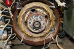
I'm talking about these guys here: (I of course removed the 8 leads before testing)

MEP802-12-6-2015-02.jpg
http://www.cstone.net/~dk/MEP802-12-6-2015-02.JPG

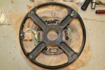
Here's that cracked bell:

MEP802-12-6-2015-03.jpg
http://www.cstone.net/~dk/MEP802-12-6-2015-03.JPG

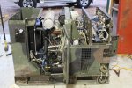
So I decided to tear into my "parts" unit:

MEP802-12-6-2015-06.jpg
http://www.cstone.net/~dk/MEP802-12-6-2015-06.JPG

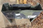
The only pieces I have stolen from it so far are the oil drain hose and the exhaust gasket. I got the control unit removed and the rear doors, frame and bell housing cover. The bell is in good shape!

MEP802-12-6-2015-07.jpg
http://www.cstone.net/~dk/MEP802-12-6-2015-07.JPG

I went ahead and pulled the end bell of this one as well. It went just as smooth as with the other one. I then tested the generator and exciter stator and rotor leads. Everything was within spec like the other unit.

So I tested the rotating rectifiers on this guy and the readings were exactly the same as the other generator. Infinity in one direction and about 1.8 Mega Ohms in the other. Are these prone to failure? What are the odds that I have 4 blown rectifiers on 2 random units?

I suppose the next step is for me to tear down the remaining 2 generators to see what condition the rectifiers on those are. I'd hate to think what they cost to replace. Part numbers are 358-0069 and 358-0070 I believe.

EDIT: Looks like Power Parts carries the diode packs for $35 each. I guess that's not that bad.
 
Last edited:
Another Ahab

Well-known member
17,999
4,556
113
Location
Alexandria, VA
I suppose the next step is for me to tear down the remaining 2 generators to see what condition the rectifiers on those are. I'd hate to think what they cost to replace. Part numbers are 358-0069 and 358-0070 I believe.
When you got them, It seems like you might as well make use of them.

I just hope you got a place to store all the parts you pull out of there. Do you?
 

Another Ahab

Well-known member
17,999
4,556
113
Location
Alexandria, VA
That is a very fine looking shop; I mean even the lighting is top-shelf. Nice. [thumbzup]

You got plenty of vertical space for everything, if only you could figure out a way to STACK all that product!
 

pclausen

Well-known member
Steel Soldiers Supporter
452
281
63
Location
Afton, VA
So I tore down the other 2 units only to find that the rectifiers in those also meassure open in one direction and about 1.8 Mega Ohms in the other. That's when I realized that I should probably be using the diode test setting instead of resistance for testing, well, diodes. aua I see Rich beat me to it.

So on the diode setting, the Fluke is showing 0.550 or so in one direction and open in the other. I think the 0.550 represents the voltage drop across the diode. So apparently all the rectifiers are good. :D

I think the issue with using the resistance setting on a DVM is that the current is so low that it just doesn't really register. An old school analog VM probably works fine for testing diodes using the resistance setting.

So the good news is that all the generators have good windings and rectifiers, the bad news is that I'm no closer to figuring out why unit #2 isn't making power. I'll put it back together and get it fired up and see if I can determine what's going on now that the basics have checked out.
 
Last edited:
jamawieb

Well-known member
1,437
556
113
Location
Ripley/TN
I found my trusty old can of Tun-O-Wash last night. It is almost full. I'll spray that stuff into all the openings I can find on both the AM/VM switch and phase selector switch and work them as you suggest. I think I did them both maybe 5 times or so already, so I'll be sure to do at least another 10 times each. :D

View attachment 597810
Wanted to let you know that I worked on my 803a that was having the overload fault reading and problems with the percent load gauge. I took the top cover off and sprayed the phase selector with electronic cleaner and wd-40 (moves freely now). After working the phase selector about 20-25 times, I no longer had the overload fault and the percent load gauge was reading a little better. At 45 amps per leg the percent load gauge was reading about 50% instead of 20%. I hope this help you, I'm going to work the phase selector and VM/AM selector some more and see if the percent load gauge gets better.
 

pclausen

Well-known member
Steel Soldiers Supporter
452
281
63
Location
Afton, VA
Thanks. I have worked those rotary switches about 30 times now and kept spraying them with the cleaner. Hopefully that will do the trick! Put on a new oil filter and added fresh oil in it. Waiting for the weekend to pull it back out again and load test it some more.

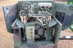
I also got the end bell back on unit #2 and stuck a control box on it. It fired right up and is now making power!

MEP802-12-8-2015-01.jpg
http://www.cstone.net/~dk/MEP802-12-8-2015-01.JPG

Most of the gauges aren't working yet, but I'll go through all that to see where the issues are. I figured once I get this control box working 100%, fixing sensors or whatever is keeping the gauges from working, I'll swap the remaining 3 control boxes onto this unit see what works and what doesn't and correct issues as I go. I can get get 4 100% working control boxes out of my 5, then I'll be happy and it will make trouble shooting the remaining 3 units much easier, knowing that my control boxes are good.
 

pclausen

Well-known member
Steel Soldiers Supporter
452
281
63
Location
Afton, VA
I went through the other 3 control boxes and 2 of them would start the generator and of those, one was making power, the other one was not. The 3rd one would not even crank the engine. The one making power was working 100% though, including the load meter and it was able to hold a 7000 watt load. This was the control box from the "parts" machine.

So I decided to take a closer look at the parts machine. I pulled off the front and and pulled the fuel tank. It actually had 3 holes drilled through it.

MEP802-12-14-2015-01.jpg
http://www.cstone.net/~dk/MEP802-12-14-2015-01.JPG

I guess they were serious about not wanting to put this particular unit back in service. When I pulled the tank, I also noticed that the low fuel level shut off control box had been pulled for some reason.

To my surprise, the engine turned over easily and the crank case was dry, as in no water. I had already been through the generator part and knew the rotating rectifiers were good, as were all the windings. So I decided to prep this one to see if it would start. With the front end removed, it was pretty clear that the front seal had been leaking badly.

MEP802-12-14-2015-02.jpg
http://www.cstone.net/~dk/MEP802-12-14-2015-02.JPG

A little degreaser and power washing helped clean up the area.

MEP802-12-14-2015-03.jpg
http://www.cstone.net/~dk/MEP802-12-14-2015-03.JPG

Pulled the crank pulley and that pretty much confirmed for sure the seal was bad.

MEP802-12-14-2015-04.jpg
http://www.cstone.net/~dk/MEP802-12-14-2015-04.jpg

Popped the front cover and found a pretty bad grove worn into the crank shaft.

MEP802-12-14-2015-05.jpg
http://www.cstone.net/~dk/MEP802-12-14-2015-05.jpg

So when I pressed the new seal into the front cover, I pressed it about 2 mm further in than the old one so that it would go past the groove. Hopefully this will prevent it from leaking again anytime soon.

MEP802-12-14-2015-06.jpg
http://www.cstone.net/~dk/MEP802-12-14-2015-06.jpg

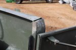
Apparently this unit suffered a pretty serious drop. Enough so that the engine rammed against the dead crank switch bracket to bend it up pretty good.

MEP802-12-14-2015-07.jpg
http://www.cstone.net/~dk/MEP802-12-14-2015-07.JPG

Also took a good hit on the frame top above the dead crank switch.

MEP802-12-14-2015-08.jpg
http://www.cstone.net/~dk/MEP802-12-14-2015-08.JPG

The front also got banged up as well.

MEP802-12-14-2015-09.jpg
http://www.cstone.net/~dk/MEP802-12-14-2015-09.JPG

One of the fins on the fan blade was also bend to the point of hitting the alternator, but that was easy enough to fix. I think I can also fix the cosmetic damage to the enclosure. It won't be perfect, but certainly should not prevent it from working correctly.

The upper bracket on the load terminal block was also bend a little, but was easy enough to correct.

MEP802-12-14-2015-10.jpg

So I'm not sure why they would have drilled the tank on this particular unit. I just got banged up a little and had a front seal leak. Of course there may be other issues, but I guess I'll find out soon enough.
 

pclausen

Well-known member
Steel Soldiers Supporter
452
281
63
Location
Afton, VA
So I got the "parts" 802 all together, new filters, oil and coolant.

MEP802-12-15-2015-01.jpg
http://www.cstone.net/~dk/MEP802-12-15-2015-01.JPG

Fortunately I used water for the coolant for now and I noticed a water leak at the water pump.

MEP802-12-15-2015-02.jpg
http://www.cstone.net/~dk/MEP802-12-15-2015-02.JPG

Water was coming out of the side weep hole. Once I plugged it, it started coming out the top one.

Bummed at the prospect of having to take the front apart again, I figured I'd go ahead and try to start it anyway. I let it prime for a couple of minutes to circulate the fuel and I could hear the return fuel trickle back into the tank. I then started cranking it for maybe 15 seconds at a time, but no dice. I was getting ready to start the bleed procedure to see if I was getting fuel on the high pressure side. So I cranked it one last time, and all of a sudden the engine sort of seized. I was able to turn it backwards with a wrench, but going forward, it now hits some sort of mechanical interference.

It was cranking fine one minute and making good compression and had all the right sounds, and now there is some sort of serious mechanical issue. I guess whatever it is, was the reason they drilled 3 holes in the fuel tank. Oh well, guess I'll need to take the head off and see what it looks like and go from there.
 

Chrispyny

Member
294
12
18
Location
NY
Standing by for head removal. Very interested to see whats going on... I hope you have the head removal as top priority. Awesome thread. Keep up the good work.
 

pclausen

Well-known member
Steel Soldiers Supporter
452
281
63
Location
Afton, VA
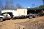
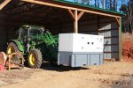
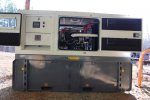
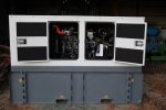
Its brand new. Picked it up this morning in Baltimore fresh off the boat from China.

36kw-27.jpg

36kw-08.jpg
http://www.cstone.net/~dk/36kw-08.JPG

I picked it up for an acquaintance that is never stateside except for maybe 3 weeks every other year or so. He wanted something to protect the valuables in his house in case of a power outage. It's a rather large house, and this 36Kw is only going to run his emergency panel (HVAC and security system). I hope to get it installed this weekend. Already have the Asco transfer switch installed and online.

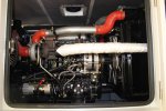
Has a 100 gallon base tank that should give it about a weeks worth of run time unattended. Engine is a YangDong YAS490ZLD turbo charged inter-cooled Perkins clone. From the research I did, the YangDong is the only Chinese engine worth considering. They are in the Jinma tractors sold here in the US, so parts are plentiful.
 

Korgoth1

New member
191
5
0
Location
radford, va
Whats the decibels on that unit? Looks like a nice attenuated enclosure...

Nevermind, looked it up. 70db at 3 meters.
 
Last edited:
Top