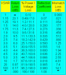
Here is a handy chart, for those of us so tightly wound as to be concerned with SWR and its effects on the system as a whole. By the way if I make any mistakes writing about radio stuff, please jump in and correct me, I do not claim to be an expert.
I shamelessly stole this from
www.ab4oj.com/atu/vswr.html where the math is gone into in some detail. This kind of charts abounds and the math is well known in the art, yet many radio operators do not observe these things.
The main figures of interest are:
1.) The leftmost column, the "VSWR" as read on the SWR meter at the antenna. (VSWR stands for voltage standing wave ratio, commonly just called SWR)
2.) The first figure in the "% Power / Voltage loss" column. It shows the % Power that is reflected back from the antenna towards the transmitter. The power is wasted as heat in the coaxial cable and inside the radio's RF power amplifier.
Always read the SWR at the antenna because a length of cable will tend to minimize the SWR observed at the transmitter
(example- The HF mast on my truck is by its own length tuned to about 22MHz (3 sections). Using it as-is for CB at 27MHz, the SWR at the antenna feedpoint would be perhaps 10 to 1 and the antenna is reflecting 67.6% of the juice back towards the radio. But not all of that energy makes it to the radio because the impedance of the antenna is not 50 ohms at 27MHz as it should be, and there is a mismatch between the antenna and the 50-ohm cable. The cable therefore also dissipates some of the energy as heat. If I have 50FT of cable between the antenna feedpoint (the terminal at the antenna base), the loss in the cable can be so great as to only allow a small amount of the reflected energy back to the radio. In the example say about 11% of the total transmitted power gets back to the radio because of a long cable. If the SWR is measured at the radio, where the reflected power is attenuated by all that cable, SWR meter will show about 2:1 SWR. -a false reading, leading the operator to believe the system is OK. This is in fact OK for the radio from a burnout standpoint, but the waste of power works both ways: the reception is also weakened considerably due to the mismatched antenna system so now the $250 Cobra 148GTL receives like the plastic $50 CB!
The secondary point of this long and tiresome post I suppose is to illustrate why the tuning mechanism is located inside the antenna base and not inside the radio.
Losses in the cable between the radio and the antenna in case of an impedance mismatch (and SWR >1) become greater as the length of the cable becomes a significant part of the length of the radio wave.
The VRC-12 radios or antennas mentioned here operate on wavelengths of 10 to 4 meters (30 to 75 MHz). A 6 FT cable becomes quite significant. 50FT of cable as I have from the front bumper to the radios in the shelter could be a communications disaster if the antenna impedance matching network was in the radio and not in the antenna.
Off the topic of the VRC-12, Other radios like the AN/GRC-106 which has a built-in operator-tuned antenna matching network operate on longer wavelengths of 150 to 10 meters (2 to 30 MHz) and the cabling may be generally longer before the VSWR causes alot of signal loss in the cable. By the way you can connect a set of bedsprings to that orange insulated terminal on the -106 and tune it up and it will work well! but don't touch the bedsprings, they might be kind of hot.
But back to the VRC radio setup, just make sure the tuning system in the antenna base is connected and working and the set will work beautifully. Got a ham license? the simplest one allows access to 50-54MHz which the VRC-12 is most useful for.


