• Steel Soldiers now has a few new forums, read more about it at: New Munitions Forums!

  • Microsoft MSN, Live, Hotmail, Outlook email users may not be receiving emails. We are working to resolve this issue. Please add support@steelsoldiers.com to your trusted contacts.

Radio setup ?

BillIdaho

Member
417
7
18
Location
Caldwell, Idaho
I would do away with the cable between the batteries and the RT524 (actually the MT1029). I would strongly reccomend the MX-7778 Suppressor. I would have to get the book out for the part number for the cable between the batteries and the MX-7778.
 

maddawg308

Well-known member
Steel Soldiers Supporter
10,865
762
113
Location
Appomattox, VA
I believe the unknown cable would be same as if you didn't use a suppressor, CX-4720/VRC. Also, I don't see any mention of a loudspeaker, but the designation would be LS-454/U for that part.
 

BillIdaho

Member
417
7
18
Location
Caldwell, Idaho
The input for the MX-7778 is the same as an MT1029, so it believe the cx-4720 is the correct cable.
I am currently wearing a pair of sweats and a t-shirt, it's about 18 degrees outside, and I'm not running outside to look.
 

Boatcarpenter

New member
1,877
17
0
Location
Marlborough, NH
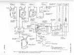
Thanks guys! I should redo the direct line from the batteries to the radio to indicate it really goes to the mount. Maybe later tonight.
What would your antenna cable and antenna base preference be?
 

Boatcarpenter

New member
1,877
17
0
Location
Marlborough, NH
Thanks Bjorn. I thought you probably had a drawing, but I thought if I spent the time figuring it out it would help me understand the system and try to learn some of the #'s. Besides, it was too cold thim AM to go right to work anyway.
 

ONTOS66

Member
433
3
18
Location
Franklin, NJ
As Bjorn pointed out, the 524 has a built in speaker. His diagram should answer most of your questions regarding installation. You can add a speaker to the crewmembers box if you don't have headsets (or don't want to wear them all the time) or just want to use a mike instead of the CVC or headset.
Have fun!
 

Boatcarpenter

New member
1,877
17
0
Location
Marlborough, NH
maddawg-OK
ONTOS66-Learning the lingo here-CVC? Also, am I correct in thinking that one ant. base is tunable, one is not. One you tune on the base and the other is tunable from the radio if so equipped.
 

OPCOM

Moderator
Steel Soldiers Supporter
3,657
27
48
Location
Dallas, Texas
The non-tunable base has merely a BNC connector on the bottom for the antenna cable, as well as a ground strap (use it!). Inside is sealed a bizzarre and mysterious matching network that should never be tampered with. Note the mast sections for the non-tunable base do not electrically work properly with the sections for the tunable bases. The non-tuning base is broadband and is the AS-3684/VRC. It doesn't offer a perfect match by any means, but generally keeps it better than 3:1 from 30-90 MHz.

If you run the RT246 ot RT524 on LOW power, a mismatch will not harm it except for the performance.
 

OPCOM

Moderator
Steel Soldiers Supporter
3,657
27
48
Location
Dallas, Texas
Ahh, the newer version. Use it in good health!

Attached is the SWR plot for the AS-3684 for those inquiring minds. Maybe someone with an MFJ-259 (or even a real piece of test gear..) can do a plot of the AS-3900A, AS-1729, or AT-912 if they get the chance. The switch would have to be turned for each range on the latter two but that's the easy part.
 

Attachments

OPCOM

Moderator
Steel Soldiers Supporter
3,657
27
48
Location
Dallas, Texas
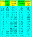
Here is a handy chart, for those of us so tightly wound as to be concerned with SWR and its effects on the system as a whole. By the way if I make any mistakes writing about radio stuff, please jump in and correct me, I do not claim to be an expert.

I shamelessly stole this from www.ab4oj.com/atu/vswr.html where the math is gone into in some detail. This kind of charts abounds and the math is well known in the art, yet many radio operators do not observe these things.

The main figures of interest are:

1.) The leftmost column, the "VSWR" as read on the SWR meter at the antenna. (VSWR stands for voltage standing wave ratio, commonly just called SWR)

2.) The first figure in the "% Power / Voltage loss" column. It shows the % Power that is reflected back from the antenna towards the transmitter. The power is wasted as heat in the coaxial cable and inside the radio's RF power amplifier.

Always read the SWR at the antenna because a length of cable will tend to minimize the SWR observed at the transmitter

(example- The HF mast on my truck is by its own length tuned to about 22MHz (3 sections). Using it as-is for CB at 27MHz, the SWR at the antenna feedpoint would be perhaps 10 to 1 and the antenna is reflecting 67.6% of the juice back towards the radio. But not all of that energy makes it to the radio because the impedance of the antenna is not 50 ohms at 27MHz as it should be, and there is a mismatch between the antenna and the 50-ohm cable. The cable therefore also dissipates some of the energy as heat. If I have 50FT of cable between the antenna feedpoint (the terminal at the antenna base), the loss in the cable can be so great as to only allow a small amount of the reflected energy back to the radio. In the example say about 11% of the total transmitted power gets back to the radio because of a long cable. If the SWR is measured at the radio, where the reflected power is attenuated by all that cable, SWR meter will show about 2:1 SWR. -a false reading, leading the operator to believe the system is OK. This is in fact OK for the radio from a burnout standpoint, but the waste of power works both ways: the reception is also weakened considerably due to the mismatched antenna system so now the $250 Cobra 148GTL receives like the plastic $50 CB!

The secondary point of this long and tiresome post I suppose is to illustrate why the tuning mechanism is located inside the antenna base and not inside the radio.

Losses in the cable between the radio and the antenna in case of an impedance mismatch (and SWR >1) become greater as the length of the cable becomes a significant part of the length of the radio wave.

The VRC-12 radios or antennas mentioned here operate on wavelengths of 10 to 4 meters (30 to 75 MHz). A 6 FT cable becomes quite significant. 50FT of cable as I have from the front bumper to the radios in the shelter could be a communications disaster if the antenna impedance matching network was in the radio and not in the antenna.

Off the topic of the VRC-12, Other radios like the AN/GRC-106 which has a built-in operator-tuned antenna matching network operate on longer wavelengths of 150 to 10 meters (2 to 30 MHz) and the cabling may be generally longer before the VSWR causes alot of signal loss in the cable. By the way you can connect a set of bedsprings to that orange insulated terminal on the -106 and tune it up and it will work well! but don't touch the bedsprings, they might be kind of hot.

But back to the VRC radio setup, just make sure the tuning system in the antenna base is connected and working and the set will work beautifully. Got a ham license? the simplest one allows access to 50-54MHz which the VRC-12 is most useful for.
 

Attachments

Boatcarpenter

New member
1,877
17
0
Location
Marlborough, NH
Thanks OPCOM! This is like an on line correspondence course! I'll have to print this one out and study up on it as this is all new to me but I get the gist of it. Certainly will help as installation rolls around when warmer weather gets here. As to a ham license, no, not yet, researching that also. You say 50-54MHz is the most useful freq. of the VRC-12. What kind of activity are we talking about, most general ham activity?
Thanks again OPCOM, this is ALL very helpful.
Boatcarpenter
 

OPCOM

Moderator
Steel Soldiers Supporter
3,657
27
48
Location
Dallas, Texas
The 6 Meter ham band from 50-54 Mhz is really the only legal place to use a VRC radio set. I guess that is why it is the most useful. Most hams use SSB or CW on that band, but there is some FM. Guys like us with the military radios definitely get licensed and use that range. some people bootleg around 49MHz where cordless phones are, but that's a little shady.

The FCC spectrum chart is here;
http://www.ntia.doc.gov/osmhome/allochrt.pdf

and the 6-meter ham radio band details are here;
http://www.arrl.org/FandES/field/regulations/bands.html

basically 50.1 to 54.0 for voice, but look closer as there are by "gentlemens agreements" certain places for each kind of commo; AM/FM/SSB/CW/data/repeaters. etc.. called the "band plan"

http://www.azfreqcoord.org/bp/6mbp.pdf

also since the VRC sets are wideband, we need to stay away from the edges of the band so we do not spill over into other services.

To get a license, take this practicee test till you can pass with a score of .80 each time, take the test a couple times a day for a week and then go take a technican license test for $15 from your local ham club, and you will be on your way.
The tests are here:
http://www.qrz.com/
scroll down the left side of the page and take the technician test.

There is not alot of activity on this band, but that is OK for when we have convoys, it is open!

Hope this helps further.
 

Boatcarpenter

New member
1,877
17
0
Location
Marlborough, NH
Thanks OPCOM. I found a site this AM and took a couple of practice tests and hit 20 and 21 out of 35 with no study etc. So there is hope with a little practice etc. I can pass!!
BC
 
Top
AdBlock Detected

We get it, advertisements are annoying!

Sure, ad-blocking software does a great job at blocking ads, but it also blocks useful features of our website like our supporting vendors. Their ads help keep Steel Soldiers going. Please consider disabling your ad blockers for the site. Thanks!

I've Disabled AdBlock
No Thanks