• Steel Soldiers now has a few new forums, read more about it at: New Munitions Forums!

  • Microsoft MSN, Live, Hotmail, Outlook email users may not be receiving emails. We are working to resolve this issue. Please add support@steelsoldiers.com to your trusted contacts.

S1 Switch Function (Auto Start) 003a

ckesey

Member
43
5
8
Location
Tennessee
I'm working on a lower cost auto-start for my 003a. From looking at the manuals (and the wiring diagram of the autostart kits) I have the wire location (terminal blocks locations) that need to be connected up.

The one thing I don't have figured out just yet is how the generator is powered off via the S1 switch (wiring wise).

From the wiring diagram is 24v always present at positions #11 and #25 and that is switch among the other terminals during pre-heat, prime, aux fuel & start?

I will do some reading with my meter when the weather breaks but thought someone could shed some light on the subject until then.
 

Attachments

Guyfang

Moderator
Staff member
Moderator
15,979
22,372
113
Location
Burgkunstadt, Germany
Go back to your TM, and look at sheet number 1-7, where you took your screen shot. Look at the lower right side corner. There is the S1 schedule. It shows what terminals are hot in what position.
 

ckesey

Member
43
5
8
Location
Tennessee
Go back to your TM, and look at sheet number 1-7, where you took your screen shot. Look at the lower right side corner. There is the S1 schedule. It shows what terminals are hot in what position.
I did not see that diagram in the lower right corner. That's what I was looking for however is there an error in the start circuit? Shouldn't that be 11-13-27 rather than 11-13-15? On mine, 15 is preheat.
 

Attachments

ckesey

Member
43
5
8
Location
Tennessee
Preheat is active in the START position as well as the PREHEAT position.
I see now. There is another set of connections made 25-27-28 that will actually engage the starter.

I'm working on a low cost raspberry pi (with some relays) for an autostart. I don't see why it wouldn't work if all that's happening here is connections are being made within the S1 switch.

Thanks for the help.
 

SandBar

Full Time Patriot
755
231
43
Location
GA/FL
I see now. There is another set of connections made 25-27-28 that will actually engage the starter.

I'm working on a low cost raspberry pi (with some relays) for an autostart. I don't see why it wouldn't work if all that's happening here is connections are being made within the S1 switch.

Thanks for the help.
Great idea, if you need any design or coding help please let me know. In fact I started on this path with an ESP32 (very capable MCU and less money) before I switched direction and got a bigger generator.
 

Scoobyshep

Well-known member
914
989
93
Location
Florida
I see now. There is another set of connections made 25-27-28 that will actually engage the starter.

I'm working on a low cost raspberry pi (with some relays) for an autostart. I don't see why it wouldn't work if all that's happening here is connections are being made within the S1 switch.

Thanks for the help.
I automated a 004 with a PLC a year ago. I cant imagine a 003 being much harder
 

nextalcupfan

Well-known member
348
506
93
Location
NW Missouri
I see now. There is another set of connections made 25-27-28 that will actually engage the starter.

I'm working on a low cost raspberry pi (with some relays) for an autostart. I don't see why it wouldn't work if all that's happening here is connections are being made within the S1 switch.

Thanks for the help.
This is exactly how I automated my 803a.
MEP Automation Install 14 (Final).jpgMEP Automation Wiring 04.jpg
 

ckesey

Member
43
5
8
Location
Tennessee
Thanks for the encouragement. I don't know much about PLCs but do know about raspberry pi's and python so I figured I would go that route.

Mentally putting it down, my logic would look something like this (welcome your input):

- Attached a sensor attached the pi that would give ambient temperature.
- Have some logic if the temperature is between x-y then preheat for x seconds (would have few different ranges here)
- Prime for 2 seconds
- Energize the crank circuit for 15 seconds (along with the prime, preheat and run circuits)
- Check for oil pressure at the TB5-9 pin (keeping the run and prime circuit energized only)
- If oil pressure- do nothing else except for keeping run & prime circuits energized (assuming generator is running at this point)
- If not preheat for x seconds (dropping the run circuit) and start the process over again at prime.
- If I were to go though 2-3 cycles and still no oil pressure stop.

For shutdown:
Removing 24v from any S1 circuits that are closed (prime,run)

My assumption would be once power is removed from S1 position 14 (or TB5-7) the generator will shutoff?

My thoughts behind using a Pi is, once I get things autostarting, I could get a little more fancy about voltage output, load, engine temp, etc.
 

Scoobyshep

Well-known member
914
989
93
Location
Florida
Keep in mind when cranking both sides of the low oil pressure switch have +24 on them (one side from s1pin 14 through k1 the other from s1pin 28 so your controller wont know that the low oil cutoff has been closed until the start command has cleared.
 

ckesey

Member
43
5
8
Location
Tennessee
Keep in mind when cranking both sides of the low oil pressure switch have +24 on them (one side from s1pin 14 through k1 the other from s1pin 28 so your controller wont know that the low oil cutoff has been closed until the start command has cleared.
So your saying I will need to stop cranking then check for oil pressure rather than trying to check while cranking?
 

Scoobyshep

Well-known member
914
989
93
Location
Florida
So your saying I will need to stop cranking then check for oil pressure rather than trying to check while cranking?
The way the unit is wired yes. There are a few work arounds, Add an aux pressure switch (though you need one that has a similar trip point) add a blocking diode to prevent the power backflow to the oil switch, or add a normally closed relay contact to do the same (closed when not cranking open when cranking)
 

ckesey

Member
43
5
8
Location
Tennessee
The way the unit is wired yes. There are a few work arounds, Add an aux pressure switch (though you need one that has a similar trip point) add a blocking diode to prevent the power backflow to the oil switch, or add a normally closed relay contact to do the same (closed when not cranking open when cranking)
Thanks for the info. That's something that would have had me chasing my tail for a little while. Since the starter disengages automatically, it seems like the simple thing to start with would be just to crank for 10-15 seconds, stop then check for voltage. Once I get things starting on their own, I may look at something a little more complex like your suggesting.
 

nextalcupfan

Well-known member
348
506
93
Location
NW Missouri

nextalcupfan

Well-known member
348
506
93
Location
NW Missouri
Thanks for the encouragement. I don't know much about PLCs but do know about raspberry pi's and python so I figured I would go that route.

Mentally putting it down, my logic would look something like this (welcome your input):

- Attached a sensor attached the pi that would give ambient temperature.
- Have some logic if the temperature is between x-y then preheat for x seconds (would have few different ranges here)
- Prime for 2 seconds
- Energize the crank circuit for 15 seconds (along with the prime, preheat and run circuits)
- Check for oil pressure at the TB5-9 pin (keeping the run and prime circuit energized only)
- If oil pressure- do nothing else except for keeping run & prime circuits energized (assuming generator is running at this point)
- If not preheat for x seconds (dropping the run circuit) and start the process over again at prime.
- If I were to go though 2-3 cycles and still no oil pressure stop.

For shutdown:
Removing 24v from any S1 circuits that are closed (prime,run)

My assumption would be once power is removed from S1 position 14 (or TB5-7) the generator will shutoff?

My thoughts behind using a Pi is, once I get things autostarting, I could get a little more fancy about voltage output, load, engine temp, etc.

My logic is,
1. Poll a GPIO pin every second, if True count to 6, if still true start generator if false reset counts (GPIO is going through one of the relays on the Pi board, this relay is powered by a 120V AC to 5V DC power supply)
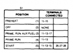
2. Set S1 to Run for 3 seconds
3. Set S1 to Start for 3 seconds
4. Wait 5 Seconds then check hour meter for power (during my initial setup this seemed to be the best place to check if the set was running. It does have a flaw though)
5. If hour meter has power let Generator warm up for 30 seconds.
6. Close AC Contactor
7. Close a relay to send 12V DC to my Generac ATS
8. House is now on Generator Power
9. Monitor the GPIO Pin from step 1 and wait for False, when power comes back count to 120, if still False Stop sending power 12V power to ATS
10. Open AC contactor
11. Let generator cooldown for 60 seconds then shutdown
12. Reset all parameters so the program starts over from the beginning.

IF power is not found on Hour Meter from step 5
1. Set S1 to off
2. Set S1 to preheat for 15 seconds
3. Set S1 to run for 3 seconds
4. Set S1 to Start for 6 seconds (added 3 seconds)
5. Check hour meter again
6. If it fails again it tries 1 more time but with 30 seconds of preheat and 9 seconds of cranking
7. If the 3rd attempt fails set everything off and print an error in the terminal with a date stamp

Now about this problem with measuring power from the hour meter to check if the engine is running, during my testing I found IF the 803a goes off on a safety it shuts off power to everything except the indicator warning panel, including the hour meter. So if the set fails to start due to low oil pressure (most often happens in the extreme cold) the program can "see" that and attempt a restart.

Now the problem, I just found out the "safeties" only come on IF the MPU disengages the starter. Meaning the engine has to "almost but not quite" start.
IF the set just cranks without even trying to start apparently the Hour Meter still has power so my program "thinks" the engine is running and continues.
I'm still working on a solution to this problem.

PLEASE keep in mind my set is an 803a, not a 003a like yours so some things will be different. I purposely didn't give exact wire numbers or terminal positions for this reason. I only hope that my thought process helps you in making your program.
 
Last edited:

nextalcupfan

Well-known member
348
506
93
Location
NW Missouri
Video Showing a simulated power failure.

Video Showing the generator failing to start and successfully retrying.

Video Showing the flaw in my program.
 

ckesey

Member
43
5
8
Location
Tennessee
Thanks for the awesome feedback here. My pi came today and I'm using a 3 relay hat (will need two of them) but wanted to do some proof of concept before purchasing everything. I was able to switch the relays very easily with very little python code. Let the wiring and coding begin.

One thing I've been thinking about is how to get the temperature (for preheat). My thought is to attach some type of sensor directly to the oil pan, etc such that if the generator is warm (from just being run, even on a cold day) it won't need the preheat cycle near as long- or at all. There is no need to preheat for 60 seconds on a cold day if the generator was just run 10 mins ago (in the situation where the power was restored but has gone out again).

Did any of you use a temperature sensor and if so where did you attach it?

Thanks,
 

Scoobyshep

Well-known member
914
989
93
Location
Florida
I would attach it to the cylinder head. You could also just go off of timing, for example 30 sec preheat, if it fails to start go for a longer preheat.

Sent from my SM-G973U using Tapatalk
 
Top