• Steel Soldiers now has a few new forums, read more about it at: New Munitions Forums!

  • Microsoft MSN, Live, Hotmail, Outlook email users may not be receiving emails. We are working to resolve this issue. Please add support@steelsoldiers.com to your trusted contacts.

Seems like this is turning into a build thread.

CARC686

Well-known member
273
484
63
Location
Las Cruces, New Mexico
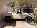
Reference image for ride height before spring replacement:
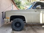
Height Reference Image.jpeg

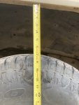
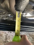
Fender to tire clearance in inches:

Tire to Fender Clearance.jpeg

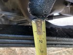
Bump stop clearance spec is 2". This truck has 3/4" of sag:
Bump Stop Clearance.jpeg

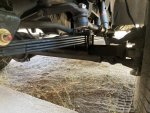
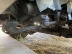
Reverse arch on 40 year old, three leaf OEM springs:
Negative Arch.jpeg

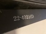
22402HD [Husky via RockAuto] replacement springs, four leaves, 1900LBS rated:
22-402HD.jpeg

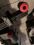
3.2105R bushing kit [Energy Suspension] installed in shackle end of springs:
[Check the instructions. These are the 2007s. The 2008s go in the top of the shackle.]
Energy Suspension.jpeg

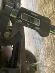
A problem. Shackle bolt diameter:

Shackle Bolt Diameter.jpeg

Inside diameter of shackle spacer provided in Energy Suspension kit:
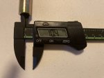
Bushing Spacer ID.jpeg

I contacted Energy Suspension via email this evening. If I don't get a timely response, I'll find somebody with a drill press to run an 11mm bit through these. The springs came with rubber bushings installed in the front eyes. I broke three drill bits off in one of them this evening. Not my proudest moment, but certainly not my worst either. The torch and reciprocating saw come out tomorrow. I'm in no rush. Will update as I go.
 

CARC686

Well-known member
273
484
63
Location
Las Cruces, New Mexico
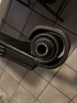
OE front spring bushing:

Before.jpeg

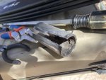
Learn from my mistake and do not use "thin metal" blades. I am the proud new owner of four butter knives after not managing to cut all the way through one bushing sleeve:

Unimpressed.jpeg

Contemplated my lack of 10 ton presses, ball joint presses, compressors, air hammers, and welders as I split and beat this thing out with a claw hammer, a screwdriver, and a 24mm socket over the course of an hour:

Carnage.jpeg

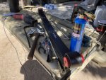
One ungodly plume of black smoke and hellacious racket later:

After.jpeg

I'll wait to do the other one. All the banging clearly irritated my neighbors. I think we could all use a break.
 

CARC686

Well-known member
273
484
63
Location
Las Cruces, New Mexico
Referred to extant online information and found that the M1009 front shackle bolt shanks are 7/16", which according to this chart, is five thou smaller than 11mm. I reckon I got my calipers buried in the threads with my 10.9mm measurement, and it's a good thing I looked it up. Saves me having to clearance them twice.

Chart.jpg

15/32" is a pretty big jump for a slip fit, but not beyond reasonable spec according to the Ames cheat sheet.

Engineering Spec.jpg

Not sure I want to snap off a cheapo Harbor Freight 15/32" drill bit in a spacer on a DIY gambit. I do have one, but I do not have a drill press or a vice, which makes farming it out an attractive option. I'll sleep on it.
 

CARC686

Well-known member
273
484
63
Location
Las Cruces, New Mexico
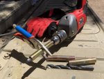
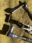
Turns out I am way too impatient to wait for a response from Energy Suspension. I tried two garages and two gunsmiths this morning and none of them wanted my money. That being the case, I went home and hogged them out with vice grips and my wrist snapper:

Wrist Snapper.jpeg

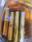
Ran the 7/16" bit through them first and a 29/64" for the second pass. The big HFT bits aren't so fragile, but the motor in the drill got hotter than hell. Since the vice grips galled the surface, I polished out the high spots with 220 emery cloth, and since I had stripped off all the zinc, I let them soak in 15w40 for an hour:

Soak.jpeg

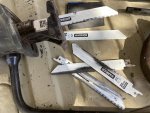
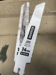
I did extract the other rubber front bushing this morning. Can confirm 14 teeth per inch is the sweet spot for metal blades on this job. I didn't even destroy one of them in the process:

14 TPI.jpeg

Brushed the leftover oil from the bushing soak onto the springs and let it soak in. They're ready to go home, and the dog is glad I'm done banging on metal with a hammer:

Prepared.jpg

Pressure washed the undercarriage this morning so hopefully I should look like a coal miner instead of looking like the Tarman from "Return of the Living Dead" when I get done installing them tomorrow:

1716232206650.png
 

CARC686

Well-known member
273
484
63
Location
Las Cruces, New Mexico
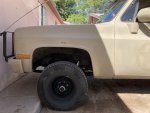
Post install reference image:

After Reference Image.jpeg

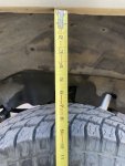
Rick is right. I wouldn't want it much taller. Was considering zero rates before, but I like not having to climb into the thing. Gained approximately 1.75" of fender clearance. I expect running 33x12.5 would be a nonissue with these springs:

Tire to Fender Clearance.jpeg

Gained approximately 1.25" bump stop clearance:

Bump Stop Clearance.jpeg

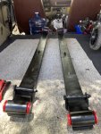
The springs don't look like recurve bows anymore:

Flat Arch.jpeg

This thing is now a tail dragger. It sits like I have a pallet of blocks in the bed. The front end is about four inches higher than the rear measured from the fender lips to the tire shoulders. Doesn't really bother me, but I will address it eventually.

Dragging Ass.jpeg

After the first drive, my impression is that these are great street springs and offer snappy steering response and tight road feel. I would not put these springs on a vehicle that spends most of its time in the dirt. I think they would beat you to death. My steering wheel is cocked to the left now, but I'll save the toe and go for after I've done the u-joint steering shaft swap. For now, I think I'll drink a gallon of water and take a nap in front of the air conditioner.
 

adf5565

Well-known member
375
688
93
Location
Tioga, PA
Post install reference image:

View attachment 923997

Rick is right. I wouldn't want it much taller. Was considering zero rates before, but I like not having to climb into the thing. Gained approximately 1.75" of fender clearance. I expect running 33x12.5 would be a nonissue with these springs:

View attachment 923998

Gained approximately 1.25" bump stop clearance:

View attachment 924000

The springs don't look like recurve bows anymore:

View attachment 923999

This thing is now a tail dragger. It sits like I have a pallet of blocks in the bed. The front end is about four inches higher than the rear measured from the fender lips to the tire shoulders. Doesn't really bother me, but I will address it eventually.

View attachment 924001

After the first drive, my impression is that these are great street springs and offer snappy steering response and tight road feel. I would not put these springs on a vehicle that spends most of its time in the dirt. I think they would beat you to death. My steering wheel is cocked to the left now, but I'll save the toe and go for after I've done the u-joint steering shaft swap. For now, I think I'll drink a gallon of water and take a nap in front of the air conditioner.
Nice work! One thing to note which took me a while to figure out, the wheel wells are lower (closer to the tire) in the rear. If you measure from the body line to the tire you’ll get a more accurate picture of true level front to back.
 

CARC686

Well-known member
273
484
63
Location
Las Cruces, New Mexico
Nice work! One thing to note which took me a while to figure out, the wheel wells are lower (closer to the tire) in the rear. If you measure from the body line to the tire you’ll get a more accurate picture of true level front to back.
Thank you. The fender gap differential is off by almost five inches, but the difference in body seam height is only 2.75". We'll see how it goes when I get around to doing new OE-style rears with poly bushings, but not anytime too soon. I'm beat.
 

nyoffroad

Well-known member
941
689
93
Location
Rochester NY
Post install reference image:

View attachment 923997

Rick is right. I wouldn't want it much taller. Was considering zero rates before, but I like not having to climb into the thing. Gained approximately 1.75" of fender clearance. I expect running 33x12.5 would be a nonissue with these springs:

View attachment 923998

Gained approximately 1.25" bump stop clearance:

View attachment 924000

The springs don't look like recurve bows anymore:

View attachment 923999

This thing is now a tail dragger. It sits like I have a pallet of blocks in the bed. The front end is about four inches higher than the rear measured from the fender lips to the tire shoulders. Doesn't really bother me, but I will address it eventually.

View attachment 924001

My steering wheel is cocked to the left now, but I'll save the toe and go for after I've done the u-joint steering shaft swap.
To center the steering wheel, loosen the lock clamp on the drag link, then with the front wheels straight and the truck running (set parking brake) turn the adjusting sleeve and the steering wheel will turn. Easy to do and no toe adjustment necessary because you never messed with it! Save the front end alignment money for something else!
 

CARC686

Well-known member
273
484
63
Location
Las Cruces, New Mexico
To center the steering wheel, loosen the lock clamp on the drag link, then with the front wheels straight and the truck running (set parking brake) turn the adjusting sleeve and the steering wheel will turn. Easy to do and no toe adjustment necessary because you never messed with it! Save the front end alignment money for something else!
That's excellent advice! Very much appreciated! Will re-center the wheel once I've installed the Jeep steering shaft. It's currently in the mail. I figure I'll document that install in this thread as bonus material. With as tight as the new springs with poly bushings feel, I'm afraid the steering will end up so tight, it'll feel weirdly out of place in an old square. The front end is already halfway to that new-car feel that I never expected to have in any old Chevy.
 

CARC686

Well-known member
273
484
63
Location
Las Cruces, New Mexico
Front end bonus round. I ordered SKP 425-284 (XJ Steering Shaft) from RockAuto. The lower bolt at the steering box is 12 point 7/16". The upper nut is 5/8" on a round headed bolt:

Hardware.jpeg

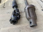
I planned to do this swap because I thought the rag joint was completely shot. I looked into replacing it with poly, but forums here and there said something along the lines of "poly is good with compressive, not twisting force". While I was looking into this, I discovered the XJ swap, which converts the shaft to u-joints. It turned out all the slop was up top in this bell-looking joint. Here's the upper comparison:

Upper Column Joint.jpeg

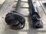
Here's the steering box end comparison. No more rag joint:

Rag Joint vs U-Joint.jpeg

Now, the shaft was about a half inch too short. I believe there are several steering shaft options for this swap. People say they have done this swap as practically a bolt-on. That was not my experience. I would recommend trying a different manufacturer, but if you go with the SKP or an equivalent, you'll have to forcibly overextend it in order to collapse it for installation, and then it will be loosened up enough to tap onto the upper column:

Instructional.jpg

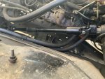
I used a little abrasive barrel on a Harbor Freight knockoff Dremel in order to create clearance for the pinch bolt at the upper column. Didn't take much and went fast and easy. Don't worry about wheel alignment. The bottom of the shaft only goes on one way and the top only goes on rightside up or upside down. The bolts were 13mm. A 1/2" wrench did not fit. Here it is in place:

Complete.jpeg

I cranked the wheels from stop to stop with the engine off and it felt sturdy. Wiggling the wheel back and forth actually wiggles the tires back and forth. Only had to drive it around the block to be shocked. There is absolutely zero steering slop. It does not feel like any old Chevy I've ever driven before.

Disclaimer: Just showing y'all what I did. Follow in my footsteps at your peril. It worked for me.
 
Last edited:

nyoffroad

Well-known member
941
689
93
Location
Rochester NY
Front end bonus round. I ordered SKP 425-284 (XJ Steering Shaft) from RockAuto. The lower bolt at the steering box is 12 point 7/16". The upper nut is 5/8" on a round headed bolt:

View attachment 924177

I planned to do this swap because I thought the rag joint was completely shot. I looked into replacing it with poly, but forums here and there said something along the lines of "poly is good with compressive, not twisting force". While I was looking into this, I discovered the XJ swap, which converts the shaft to u-joints. It turned out all the slop was up top in this bell-looking joint. Here's the upper comparison:

View attachment 924178

Here's the steering box end comparison. No more rag joint:

View attachment 924179

Now, the shaft was about a half inch too short. I believe there are several steering shaft options for this swap. People say they have done this swap as practically a bolt-on. That was not my experience. I would recommend trying a different manufacturer, but if you go with the SKP or an equivalent, you'll have to forcibly overextend it in order to collapse it for installation, and then it will be loosened up enough to tap onto the upper column:

View attachment 924180

I used a little abrasive barrel on a Harbor Freight knockoff Dremel in order to create clearance for the pinch bolt at the upper column. Didn't take much and went fast and easy. Don't worry about wheel alignment. The bottom of the shaft only goes on one way and the top only goes on rightside up or upside down. The bolts were 13mm. A 1/2" wrench did not fit. Here it is in place:

View attachment 924181

I cranked the wheels from stop to stop with the engine off and it felt sturdy. Wiggling the wheel back and forth actually wiggles the tires back and forth. Only had to drive it around the block to be shocked. There is absolutely zero steering slop. It does not feel like any old Chevy I've ever driven before.

Disclaimer: Just showing y'all what I did. Follow in my footsteps at your peril. It worked for me.
I just want to make sure you know!
Two things I see and hope neither give you a problem. #1 the OEM connection to the gear box is splined and that Jeep one is not. does the pinch bolt ride on a 'flat' of the shaft? If not I would refrain from turning the wheel without power steering and try to do so only when moving.
#2 Is there a collapsible portion on that Jeep shaft? The OEM has a ( IIRC ) shear rivet holding the two half's together. The reason that is important is in a front end collision the steer column shaft can be turned into a spear!
With that in mind I still like the mod and it looks great!
 

CARC686

Well-known member
273
484
63
Location
Las Cruces, New Mexico
I just want to make sure you know!
Two things I see and hope neither give you a problem. #1 the OEM connection to the gear box is splined and that Jeep one is not. does the pinch bolt ride on a 'flat' of the shaft? If not I would refrain from turning the wheel without power steering and try to do so only when moving.
#2 Is there a collapsible portion on that Jeep shaft? The OEM has a ( IIRC ) shear rivet holding the two half's together. The reason that is important is in a front end collision the steer column shaft can be turned into a spear!
With that in mind I still like the mod and it looks great!
I couldn't have installed it if it wasn't collapsible. Well, I could, but I'm in no mood to be pulling steering gearboxes today. That's a whole big production, but this is just a two beer job if you work slow and drink fast. The Jeep shaft telescopes at the rubber boot. It has splines that perfectly match the GM steering box output shaft. I'm just a bad photographer. I promise you there are teeth in there.

I'm still getting used to it. Never even noticed I habitually sawed at the steering wheel until it was no longer necessary. Getting a weird feeling like I'm robbing my jalopy of all its hard-earned sloppy. With the new springs, poly bushings, and u-joint steering shaft, it feels like a new truck with a rack and pinion. At least compared to before. One thing's for sure. Everything that's brand new makes everything that isn't feel like a bowl of mush.
 

CARC686

Well-known member
273
484
63
Location
Las Cruces, New Mexico
Discovered this morning that the bottom bracket on the power steering pump had fallen off. Thankfully, it had just rotated out of position, rather than being missing entirely. Don't know how long it had been like that, but the top of the pulley had worn a groove into the mount and the bottom of the pulley was less than 1mm from the hard lines. Luckily, it doesn't appear to have ever touched them. Thanks to @cucvrus for sending me the extra hardware. I used it here. After I got that sorted out, I did the transmission mounts.

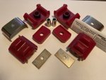
Held the assembly up with a floor jack on the transfer case tail housing. The nuts on the crossmember to frame rail fasteners are 11/16". The transmission mount bolts are 3/4". The transfer case skid plate nuts and bolts are both 9/16". The old mounts somehow managed to be both dry rotted and oil swollen at once with the consistency of marshmallows. The Energy Suspension mounts slipped right into place, fit tight, and I actually enjoyed installing them. Everything went right with no complications. It happens once in a while. No change in vibrations or road feel. I'm waiting for new motor mount bolts before I do the rest.

Discovered I have no reverse lights while changing the rears to LED bulbs this morning. Will track that issue down later. Flash interval is somewhat faster, though I doubt many people would notice. I will not be installing a resistor. I'm in it for reducing electrical load. Couldn't say if they're brighter or not. They are perfectly visible at mid-day in the desert sun. Don't know what more you could want.

New rear springs were sitting on my porch when I got home. Husky 22-403, 2350LBS rated, six leaf, made in Colombia. I figure I'll give the OE rubber a chance to collapse before swapping to poly. My wallet will thank me in the immediate term. Moved around a bunch of heavy stuff this morning and my back was polite enough to issue a warning instead of just blowing out, so I'll be taking it easy for a little bit. For now, it's Beer:30.
 

nyoffroad

Well-known member
941
689
93
Location
Rochester NY
" New rear springs were sitting on my porch when I got home. Husky 22-403, 2350LBS rated, six leaf, made in Colombia " WOW, here I thought coffee and cocaine was about all that came from Colombia!
I was under my long LONG term project and noticed the tranny mounts also oil soaked and dry rotted, didn't think of marshmallows, more of aww crap.
 

CARC686

Well-known member
273
484
63
Location
Las Cruces, New Mexico
Seemed like an odd place. They probably just have cheaper labor than China. Please refrain from discussing narcotics in my threads. The only thing hard about doing the mounts is the crud falling in your face. The Energy Suspension mounts are more expensive than I expected, but I practically got my mounts for free in what was probably a mistake where a full kit was priced like a single motor mount.
 

CARC686

Well-known member
273
484
63
Location
Las Cruces, New Mexico
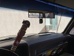
As far as cheap junk from China goes, this panoramic clip-on mirror was worth every penny. Visibility and clarity were both substandard with the OEM mirror. It was pretty scratched up among other problems. With this thing, I just rotated it until I wasn't looking at my own reflection and now have 100% visibility through the rear window and the passenger quarter glass. Not recommended if you use your sun visors. They can't even clear the stock mirror.

IMG_0565.jpeg

Does anybody know of any quality saddle blanket-style fitted seat covers that work well with the OEM buckets? There's a lot of paper-thin rubbish on the market. Looking for something I'll never have to think about again after installation.
 

CARC686

Well-known member
273
484
63
Location
Las Cruces, New Mexico
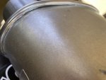
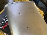
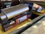
Running a HMMWV IP because it's all I could find at the time. The timing is turned up pretty good and the intake is wide open, but it could still benefit from moving more air. Preferably without sounding obnoxious. Dynomax Super Turbos seemed to fit the bill, so I ordered a couple, and they arrived this afternoon. My first impression is that they are not especially well-built. Looks like they're stamped out on a sloppy press and minimally spot welded.

IMG_0570.jpeg

IMG_0569.jpeg

I could do without the embossed branding if it got me some better build quality.

IMG_0566.jpeg

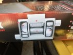
...but the thing that really puzzles me is this diagram printed on the side of the box:

IMG_0567.jpeg

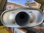
...versus the fact that these mufflers are center inlet:

IMG_0568.jpeg

I would really like to split one of these to see what's actually inside it, but even though they're relatively inexpensive and of suspect quality, they are brand new and I intend to use them. Maybe see if a welder I know will run beads around the crimps and slip fits first.

I'll hand in a sound and butt dyno report whenever I get around to installing these, but my gut tells me to recommend going with something else.
 
Last edited:

CARC686

Well-known member
273
484
63
Location
Las Cruces, New Mexico
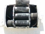
It's even worse than I suspected. I had to go digging quite a bit in search results to find this:

1717102447577.jpeg

Center inlet Dynomax Super Turbos have an atrocious baffle design. I'm experiencing secondhand embarrassment for whoever engineered this mess. Will open them up and modify them somehow. There's no way I'd install these on anything as-is. In the reviews on Summit, someone stated that these blow out a ton of fiberglass during break in. I'll bet. Blowing out the packing is the only way the exhaust can escape.
 
Top
AdBlock Detected

We get it, advertisements are annoying!

Sure, ad-blocking software does a great job at blocking ads, but it also blocks useful features of our website like our supporting vendors. Their ads help keep Steel Soldiers going. Please consider disabling your ad blockers for the site. Thanks!

I've Disabled AdBlock
No Thanks