• Steel Soldiers now has a few new forums, read more about it at: New Munitions Forums!

  • Microsoft MSN, Live, Hotmail, Outlook email users may not be receiving emails. We are working to resolve this issue. Please add support@steelsoldiers.com to your trusted contacts.

Transfer case help….M1078 2001

Ronmar

Well-known member
3,886
7,553
113
Location
Port angeles wa
This could be as simple as that C7 valve down in the transfer not opening fully. If it were something else leaking I would expect to see a significant drop on main pressure, but if it was driving thru gears fine in mode it does not sound like that was the case...
 

Xengineguy

Well-known member
Supporting Vendor
228
776
93
Location
USA Indiana
This could be as simple as that C7 valve down in the transfer not opening fully. If it were something else leaking I would expect to see a significant drop on main pressure, but if it was driving thru gears fine in mode it does not sound like that was the case...
I’ve got several calls into Allison and transfer case rebuilders, so far no one can provide info on c7 valve body gasket?? The exploded views don’t show c7 valve body in place or the attaching bolts or gasket if there is one?? Hope to hear something tomorrow?
I have removed c7 valve body, disassembled and cleaned lubed etc. I couldn’t see anything wrong with it. The screen in the solenoid
was spotless perfect. O well a least I got the locker installed in the rear differential!
 

Ronmar

Well-known member
3,886
7,553
113
Location
Port angeles wa
I’ve got several calls into Allison and transfer case rebuilders, so far no one can provide info on c7 valve body gasket?? The exploded views don’t show c7 valve body in place or the attaching bolts or gasket if there is one?? Hope to hear something tomorrow?
I have removed c7 valve body, disassembled and cleaned lubed etc. I couldn’t see anything wrong with it. The screen in the solenoid
was spotless perfect. O well a least I got the locker installed in the rear differential!
Did you ever resolve this? Was backing up in the snow into my garage today and discovered I only had the 70/30AWD split in mode… the TCU is monitoring a good circuit thru the solenoid(threw a code when I disconnected it), so either the TCU isnt sending the signal, or the valve is not opening when commanded, or something is leaking.

what size were the test ports?.
 

Skyhawk13205

Well-known member
159
270
63
Location
Alaska
Did you ever resolve this? Was backing up in the snow into my garage today and discovered I only had the 70/30AWD split in mode… the TCU is monitoring a good circuit thru the solenoid(threw a code when I disconnected it), so either the TCU isnt sending the signal, or the valve is not opening when commanded, or something is leaking.

what size were the test ports?.
Ron, are you running eco hubs? Do you think the higher torque to the C7 clutch pack is causing them to slip? There is no indication or monitoring of the C7 clutch pressures.
 

Skyhawk13205

Well-known member
159
270
63
Location
Alaska
Did you ever resolve this? Was backing up in the snow into my garage today and discovered I only had the 70/30AWD split in mode… the TCU is monitoring a good circuit thru the solenoid(threw a code when I disconnected it), so either the TCU isnt sending the signal, or the valve is not opening when commanded, or something is leaking.

what size were the test ports?.
Did you check what code? I don’t think the solenoid is monitored by the TCU, the only thing that I would think is the output speed sensor would fault when disconnected.
 

Ronmar

Well-known member
3,886
7,553
113
Location
Port angeles wa
Dont have them on yet. It has had to wait untill i could get my cab suspension fabricated. The C7 pressure isnt monitored, which is why I will need to hook up a pressure gauge. The solenoid electrical circuit is Monitored, Which is how I know it has a good circuit, because it sets a 45-23 code(H solenoid circuit open) when I unplug it. Unfortunately this makes testing the circuit activation signal more difficult, because as soon as it senses a bad circuit, it disables the diff-lock output. So I will need to either probe the wires, or connect the circuit to an appropriate resistance relay Coil. There is an alternate circuit in the wiring Allison specs to drive a diff-lock light. We use that circuit and relay K34 on the FMTV to control the power divider lockup in mode on the 6X trucks, but this wont tell me the signal is being sent to the transfer diff solenoid, or if the solenoid is acting upon it, so still need to monitor that signal and C7 pressure… which is why I need to ID the test port fitting.
It Looks about the size of a -4 SAE, but I haven't pulled a plug yet… that would be convenient as I already have everything I need to gauge a -4 port.
 

GeneralDisorder

Well-known member
Steel Soldiers Supporter
2,081
5,316
113
Location
Portland, OR
Have you checked the transmission drain plug magnets and the scavenge line screens etc?

I mean - the propensity for thrust bearing failures on these is the most obvious and likely scenario. Which would likely loosen up the clutch pack to the point where it couldn't engage even with good pressure. Solenoid is electrically good - could be mechanically broken, jammed with debris, etc but then the question is where did the debris come from and we're right back to scenario #1 again.

Do these use the solenoid to apply pressure to the C7 clutch or do they use the solenoid to dump pressure away from the C7? Some AWD systems such as the Subaru automatic transmission rear output "transfer clutch" use the solenoid to dump pressure away from the clutch piston so if you cut the signal to the solenoid or the solenoid electrically fails then the transmission locks into 50/50 4WD instead of computer controlled AWD. Which is a nice failsafe mode IMO.
 
Last edited:

Ronmar

Well-known member
3,886
7,553
113
Location
Port angeles wa
Have you checked the transmission drain plug magnets and the scavenge line screens etc?

I mean - the propensity for thrust bearing failures on these is the most obvious and likely scenario. Which would likely loosen up the clutch pack to the point where it couldn't engage even with good pressure. Solenoid is electrically good - could be mechanically broken, jammed with debris, etc but then the question is where did the debris come from and we're right back to scenario #1 again.

Do these use the solenoid to apply pressure to the C7 clutch or do they use the solenoid to dump pressure away from the C7? Some AWD systems such as the Subaru automatic transmission rear output "transfer clutch" use the solenoid to dump pressure away from the clutch piston so if you cut the signal to the solenoid or the solenoid electrically fails then the transmission locks into 50/50 4WD instead of computer controlled AWD. Which is a nice failsafe mode IMO.
There is no debris in the case or strainer, drained it this summer confirming speed sensor source and tooth count.

Dont think they are a failsafe config, i guess I will be finding out.

I did notice the controller output for the diff-lock light(wire 125), that we use to control the power divider is inverse. It completes a circuit to ground when mode/diff-lock is not selected, and removes that circuit when mode/diff-lock IS selected. So we run it thru K34 and use the de-energized contacts(30-87A) to activate the power divider air valve when the TCU enters mode and de-energizes K34...

Do you know the pressure test port size off the top of your head?
 

GeneralDisorder

Well-known member
Steel Soldiers Supporter
2,081
5,316
113
Location
Portland, OR
Do you know the pressure test port size off the top of your head?
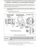
Allison Pressure Test Ports.jpg

Which I believe is just a fancy/generic way of saying -4 ORB. Looks like ORB will work unless the o-ring chamfer isn't correct to provide the seal.

Appendix B of the troubleshooting manual. Found it here:


Unfortunately - while the manual covers our transmissions (well mine anyway - the 3700SP, and I'm assuming the MD3070 is essentially the same) - there's only 9 occurrences of the term "C7" in the whole manual and no chart I can find that covers what the pressure should be. Since there's a "MAIN" port right above it I'm assuming the solenoid just opens and sends full pump pressure to the clutch for lockup.... I need to read more on the theory of operation to know for sure though since the manual doesn't seem to spell it out with a cursory search term inspection.
 
Last edited:

Ronmar

Well-known member
3,886
7,553
113
Location
Port angeles wa
View attachment 914908

Which I believe is just a fancy/generic way of saying -4 ORB. Looks like ORB will work unless the o-ring chamfer isn't correct to provide the seal.

Appendix B of the troubleshooting manual. Found it here:


Unfortunately - while the manual covers our transmissions (well mine anyway - the 3700SP, and I'm assuming the MD3070 is essentially the same) - there's only 9 occurrences of the term "C7" in the whole manual and no chart I can find that covers what the pressure should be. Since there's a "MAIN" port right above it I'm assuming the solenoid just opens and sends full pump pressure to the clutch for lockup.... I need to read more on the theory of operation to know for sure though since the manual doesn't seem to spell it out with a cursory search term inspection.
You know I have looked at that diagram in appendix B of the troubleshooting manual about a hundred times over the years and never managed to pull that 7/16-20 note out of it:) thats exactly what I needed, thanks…

1/4” or -4 ORB, same as what is on our hydraulic cylinders. Have plenty of those adapters ORB to JIC and hoses to get out to a gauge in a comfortable spot…

yea the closest the pressure spec chart lists to the diff-lock is “D‘box main” in the far right column for the 3070..
 

Xengineguy

Well-known member
Supporting Vendor
228
776
93
Location
USA Indiana
Did you ever resolve this? Was backing up in the snow into my garage today and discovered I only had the 70/30AWD split in mode… the TCU is monitoring a good circuit thru the solenoid(threw a code when I disconnected it), so either the TCU isnt sending the signal, or the valve is not opening when commanded, or something is leaking.

what size were the test ports?.
I haven’t got back to that problem yet. From what I’ve read it looks like the c7 solenoid is powered 12 volt. Not duty cycled?
I haven’t checked yet but will when it warms up a little. I now have a second truck and can swap parts if needed. Also should have a known good electrical to compare it too. These trucks keep you busy at least!
 

Ronmar

Well-known member
3,886
7,553
113
Location
Port angeles wa
Ok after checking today i see no signal change of state when selecting or de-selecting mode so I am going to have to look into this further. What I do see is 7.4Khz pulsed at a 29% duty cycle whenever the ignition is turned on. Allison uses a 2 stage peak and hold Pulse Width Modulation scheme. ~60hz with a stepped duty cycle to modulate the solenoid pull-in and a ~7KHZ at a fixed duty cycle to hold the solenoid with less heat buildup. seeing the 7.4Khz/29% makes me think they are using PWM peak and hold on the C7 lockup, but the 7.4K signal might also be how they test the circuit. Me seeing no change of state with mode is what is bothering me right now. it may also be so brief that I am not seeing it with the meter, so I may need to put a O-scope on it.

I have had mode in the past as I have dug holes with the front axle pulling stumps. I am going to check and see if I see any change of state on the aux output or perhaps I missed something with my VIM delete that the TCU needs to enable mode, although the mode on indicator does come on… Or I have a TCU output issue… More to follow.
 

Ronmar

Well-known member
3,886
7,553
113
Location
Port angeles wa
I checked the diff-lock light/power divider signal(wire 125) and it is also not changing state with mode either, but the trans display indicates mode and shifts to the 5 speed limit… this is starting to look like TCU output for my issue, grumble grumble. I will pull the TCU out and see if I can track down the circuit The low 2.5-5 Ohm solenoid coil impedance spec(mine is 3.3Ohm) pretty much confirms the diff-lock uses the peak and hold PWM scheme employed by Allison for the rest of the shifting.

i pulled the clutch test port plug and injected some pressure and I could feel the center diff lockup while rocking the front yoke, so the mechanical end of the equation seems OK…
 

Skyhawk13205

Well-known member
159
270
63
Location
Alaska
I checked the diff-lock light/power divider signal(wire 125) and it is also not changing state with mode either, but the trans display indicates mode and shifts to the 5 speed limit… this is starting to look like TCU output for my issue, grumble grumble. I will pull the TCU out and see if I can track down the circuit The low 2.5-5 Ohm solenoid coil impedance spec(mine is 3.3Ohm) pretty much confirms the diff-lock uses the peak and hold PWM scheme employed by Allison for the rest of the shifting.

i pulled the clutch test port plug and injected some pressure and I could feel the center diff lockup while rocking the front yoke, so the mechanical end of the equation seems OK…
The driveline test used just battery voltage but it looks like the solenoid/wiring overheated but it worked for the test duration. It seems like everything is driven by PWM now, it would be nice to find a PWM generator ground test.73BCE281-AF15-411F-BB38-5EF9360102EC.jpeg
 

Ronmar

Well-known member
3,886
7,553
113
Location
Port angeles wa
You would need to limit current flow with direct DC otherwise you would cook the low impedance C7 solenoid coil. i am not sure if the C7 solenoid valve vents when open, but I was able to feed air into the clutch port and engage it, with little apparent leak-down, and the air I shot in blew right back out when I lifted the blowgun off of the port. Based on that test, there is a fairly easy way to mechanically control, you have the main and clutch test ports on the transfer case. A jumper line and a valve would appear to manually lockup the center diff… for that matter a high impedance solenoid valve on that bypass line could be controlled by direct DC…

A PWM circuit is not all that difficult. You only really need 3 modes in this instance, off, brief high duty cycle to pull in the solenoid and a lower holding duty cycle to hold the solenoid open. A standalone 4WD switch actually appeals to me:)
 

GeneralDisorder

Well-known member
Steel Soldiers Supporter
2,081
5,316
113
Location
Portland, OR
Interesting that they use the peak and hold PWM control style. I wonder if these low impedance solenoids are considered a more reliable component. The consumer side of things - injectors and most valve body control solenoids in automotive - are generally high impedance since the late 1990's. They do seem to be pretty unreliable in heavy use cases though. To this day we see problems with high impedance solenoids - things like torque converter clutch solenoids on modern cars seem to be a high failure rate component - they are universally high impedance though - generally being about 33 to 37 Ohms or so. :unsure:
 

Ronmar

Well-known member
3,886
7,553
113
Location
Port angeles wa
Low impedance and peak/hold PWM to vary the current allowed more rapid and precise control.

it makes sense to have just one control scheme and stick with it, even though the C7 solenoid really only needs to be an on/off. In the 3060 troubleshooting manual it states that the H solenoid(3060 retarder/3070 diff-lock) is a higher impedance 30 Ohm coil. But the 34-1 manual specs the H/C7 solenoid as low impedance(2.5-5), mine reading 3.3 has me leaning toward the info in the 34-1 being the most accurate…

I still need to look at the cab/TCU wiring but I have not done anything there except remove the TCU for a dash makeover… I don’t think my VIM delete had anything to do with it as there are only 5 circuits not connected and they all feed the other VIM relay coils or a DNS light(not used), either to ground or 24V, and I can simulate those connections fairly easily in case the TCU is looking for/monitoring those connections… I did this with the power divider control and my test relay energized as soon as TCU was turned on(which tells me the TCU output was programmed), but it did not de-energize with mode selection as it should have… so either something is inhibiting it, but the display indicates mode on, or the output driver is not functioning, or i am not seeing the signal to engage the solenoid and it is not engaging, but since the power divider circuit is also not cycling, i don’t think this is the case…
 

Ronmar

Well-known member
3,886
7,553
113
Location
Port angeles wa
Ok, MY 4WD problem is solved. It was my VIM delete. A friend of mine shared some info about an issue he heard of where the 4WD failure turned out to be a bad 161-163 circuit. This pointed me back toward the VIM as that circuit does go thru the VIM. I misidentified that circuit when I did my VIM delete research as something to do with the PTO, and disregarded it as I don’t have a PTO, and it didn’t come up again in the WTEC 3 wiring which I was mimicking. On the A0 with WTEC2, they did 4WD like they did PTO. You send a PTO request signal to the TCU, the TCU in turn closes an output relay to send power to the PTO solenoid if it is happy with the current state of operation.

On the A0 WTEC2, you send a request to the TCU for 4WD/Mode Using the mode button. This changes the gear listing and The TCU in turn closes a relay via wire 114, which sends transmission signal ground(wire 161) to the retarder enable input 163. We use the retarder solenoid circuit H to control the center differential… Clipped a relay into that circuit, selected mode and the relay energized enabling the center diff using sig ground(161) to retarder enable 163…

i am going to do a little more research on how I will re-implement this, either add a relay to the panel or add a latching switch to control 4WD…

@Xengineguy Now that mine is working I will hook up my test connection again and document what the signal going to the C7 solenoid actually consists of in mode, and post that information here…
 
Top
AdBlock Detected

We get it, advertisements are annoying!

Sure, ad-blocking software does a great job at blocking ads, but it also blocks useful features of our website like our supporting vendors. Their ads help keep Steel Soldiers going. Please consider disabling your ad blockers for the site. Thanks!

I've Disabled AdBlock
No Thanks