• Steel Soldiers now has a few new forums, read more about it at: New Munitions Forums!

  • Microsoft MSN, Live, Hotmail, Outlook email users may not be receiving emails. We are working to resolve this issue. Please add support@steelsoldiers.com to your trusted contacts.

Transfer case help….M1078 2001

Xengineguy

Well-known member
Supporting Vendor
229
779
93
Location
USA Indiana
Ok, MY 4WD problem is solved. It was my VIM delete. A friend of mine shared some info about an issue he heard of where the 4WD failure turned out to be a bad 161-163 circuit. This pointed me back toward the VIM as that circuit does go thru the VIM. I misidentified that circuit when I did my VIM delete research as something to do with the PTO, and disregarded it as I don’t have a PTO, and it didn’t come up again in the WTEC 3 wiring which I was mimicking. On the A0 with WTEC2, they did 4WD like they did PTO. You send a PTO request signal to the TCU, the TCU in turn closes an output relay to send power to the PTO solenoid if it is happy with the current state of operation.

On the A0 WTEC2, you send a request to the TCU for 4WD/Mode Using the mode button. This changes the gear listing and The TCU in turn closes a relay via wire 114, which sends transmission signal ground(wire 161) to the retarder enable input 163. We use the retarder solenoid circuit H to control the center differential… Clipped a relay into that circuit, selected mode and the relay energized enabling the center diff using sig ground(161) to retarder enable 163…

i am going to do a little more research on how I will re-implement this, either add a relay to the panel or add a latching switch to control 4WD…

@Xengineguy Now that mine is working I will hook up my test connection again and document what the signal going to the C7 solenoid actually consists of in mode, and post that information here…
That would be great! I had mine in the shop today again. Checked the c7 coil and it seems to be very low impedance also. Checked
voltage to the coil was a little over 26v idle in mode. Checked the top of the coil with a feeler gauge for magnetism, none.
I didn’t have my scope at home but I can’t believe it’s 24v straight voltage . The coil would last about a second.
Mine also Set a code with just the c7 coil disconnected. Mine is a 2001 a1
 

Ronmar

Well-known member
3,934
7,624
113
Location
Port angeles wa
@Xengineguy
Ok, i got a chance to take some readings. I don't have a 3 Ohm injector or solenoid to measure into so these were taken into a 85 Ohm 12v relay coil. Readings taken with a Fluke 87.

My A0 WTEC2 TCU won’t enable diff lock until the engine is running.

with the ignition on I get 61 milivolts @7.3Khz ~20% duty cycle. This is such a low input, there is basically no DC component. I believe this is the supervisory signal.
when I select mode the voltage jumps up to around 15V AC over about 3/4 of a second then settles at ~11VAC @ 7.3KHZ ~20% duty cycle.
During that first 3/4 second the duty cycle ramped up from 20% to over 50% then back to 20%, which looks like a peak and hold profile to me…
 

AdiBarbu

New member
18
7
3
Location
BC , Canada
C
Ok, MY 4WD problem is solved. It was my VIM delete. A friend of mine shared some info about an issue he heard of where the 4WD failure turned out to be a bad 161-163 circuit. This pointed me back toward the VIM as that circuit does go thru the VIM. I misidentified that circuit when I did my VIM delete research as something to do with the PTO, and disregarded it as I don’t have a PTO, and it didn’t come up again in the WTEC 3 wiring which I was mimicking. On the A0 with WTEC2, they did 4WD like they did PTO. You send a PTO request signal to the TCU, the TCU in turn closes an output relay to send power to the PTO solenoid if it is happy with the current state of operation.

On the A0 WTEC2, you send a request to the TCU for 4WD/Mode Using the mode button. This changes the gear listing and The TCU in turn closes a relay via wire 114, which sends transmission signal ground(wire 161) to the retarder enable input 163. We use the retarder solenoid circuit H to control the center differential… Clipped a relay into that circuit, selected mode and the relay energized enabling the center diff using sig ground(161) to retarder enable 163…

i am going to do a little more research on how I will re-implement this, either add a relay to the panel or add a latching switch to control 4WD…

@Xengineguy Now that mine is working I will hook up my test connection again and document what the signal going to the C7 solenoid actually consists of in mode, and post that information here…
Can you post some pictures with what you did to make that C7 to engage? I have same problem, no 50/50 when push mode. Front driveshaft is rocking but no continuos power. Thank you.
 

Ronmar

Well-known member
3,934
7,624
113
Location
Port angeles wa
'95 1078 A0 wtec ii, 3116.
OK, if you are in drive, when you select mode does the display change from 2-7 to 2-5(range pre-select)?

like I described above when you select mode the only thing the transmission does is limit your gear range to 5th gear. when it does this, it outputs a mode indicator signal(path to ground) on wire 114.

On the A0 truck with the WTEC2, Wire 114 goes to the Vehicle Interface Module(VIM) under the passenger dash. It connects to a coil of relay SF01 in the VIM, with 24v on the other side. So when you select mode that relay should energize.

SF01 when energized connects transmission wire 163(4x4 engage request) to wire 161(signal ground). Telling the transmission controller to lockup the center differential.

The first check I would do is remove the passenger kickpanel and remove the cover of the VIM module. Locate SF01 in the VIM, start the truck and while holding your finger on that relay, select mode and see if it energizes. If not, you need to figure out why. If it does energize, you need to confirm that when energized it connects wire 161 to 163.

you could also pull the SF01 relay and install a jumper between pin 30 and 87 in the SF01 socket. This should engage 4x4 and lockup the center diff if that circuit is complete back to the trans controller…
 

AdiBarbu

New member
18
7
3
Location
BC , Canada
OK, if you are in drive, when you select mode does the display change from 2-7 to 2-5(range pre-select)?

like I described above when you select mode the only thing the transmission does is limit your gear range to 5th gear. when it does this, it outputs a mode indicator signal(path to ground) on wire 114.

On the A0 truck with the WTEC2, Wire 114 goes to the Vehicle Interface Module(VIM) under the passenger dash. It connects to a coil of relay SF01 in the VIM, with 24v on the other side. So when you select mode that relay should energize.

SF01 when energized connects transmission wire 163(4x4 engage request) to wire 161(signal ground). Telling the transmission controller to lockup the center differential.

The first check I would do is remove the passenger kickpanel and remove the cover of the VIM module. Locate SF01 in the VIM, start the truck and while holding your finger on that relay, select mode and see if it energizes. If not, you need to figure out why. If it does energize, you need to confirm that when energized it connects wire 161 to 163.

you could also pull the SF01 relay and install a jumper between pin 30 and 87 in the SF01 socket. This should engage 4x4 and lockup the center diff if that circuit is complete back to the trans controller…
Yes, when I press MODE, the display changes 2-5 both stationary or while driving.

I have a patch of ice in my yard where the truck wont move, only spin both rear wheels (I have locker on rear). It is how I found out about the problem. So when I hit mode, still none of the front wheels spins, no matter if I hit the gas, even in 1st. I noticed, that when I hit the mode button, the front driveshaft tries to spin, but only for 1/8 of a turn, then releases. When I turn off the MODE, the front driveshaft stays still. I hit MODE then the front driveshaft starts its pulsations but not turning. The truck otherwise drives normally. Without that patch of ice, I would not know about the problem. With a prybar I tried to spin the front shaft while engine is off and the driveshaft wont spin, so no broken driveline.

I already pulled the VIM out and could hear and feel a relay working in there but I could not determine which one so I switched around relays with same numbers, to make sure it is not a bad relay. No luck. Now I know SF01 is the one. I will find Wires 161 and 163 to confirm connection. Thank you.

I also removed the the harness from transfer case to measure if any voltage goes in there and I had the error code on transmission display for lost C7 solenoid. Then the pulsations in front driveshaft when I hit mode, so I assume the signal riches the C7 Solenoid.

I also pulled out thru inspection plate the Valve body for C7, I have 3.6 Ohms and I energized it and seems to open a small orifice. All looks good to me inside there.

I did not do pressure tests for clutch because I don't have the means but I ordered a hydraulic tester kit, so In about a week I should be able to check the pressures. How many PSI I should have in Main and in Clutch ports?

Any ideas of what else I should check and look?

Thank you so much for the valuable input and your time.
 

Ronmar

Well-known member
3,934
7,624
113
Location
Port angeles wa
Sounds like you are following the right path.

Be carefull energizing the trans solenoid coils. They use low impedance coils(3 ohm) so they can responde faster, but you must use pulse width modulation signal as direct DC(100% duty cycle) will feed them too much current and cook them… The Allison uses a 7Khz pulse signal to controll all the solenoids, and it passes a very low pulse width signal all the time to confirm that the coil circuit is OK which is why you got a fault when you unplugged it. 3.6ohm sounds OK…

the output speed/speedometer signal also rides thru that transfer case connector and you would have gotten a ratio fault if you try to drive with it disconnected.

there is a C7 clutch pressure port on the front of the transfer case. Pressure or no pressure at that port in mode will tell you where to go next. Pressure feed bad or if pressure feed is OK, C7 clutch pack failed…
 

AdiBarbu

New member
18
7
3
Location
BC , Canada
Sounds like you are following the right path.

Be carefull energizing the trans solenoid coils. They use low impedance coils(3 ohm) so they can responde faster, but you must use pulse width modulation signal as direct DC(100% duty cycle) will feed them too much current and cook them… The Allison uses a 7Khz pulse signal to controll all the solenoids, and it passes a very low pulse width signal all the time to confirm that the coil circuit is OK which is why you got a fault when you unplugged it. 3.6ohm sounds OK…

the output speed/speedometer signal also rides thru that transfer case connector and you would have gotten a ratio fault if you try to drive with it disconnected.

there is a C7 clutch pressure port on the front of the transfer case. Pressure or no pressure at that port in mode will tell you where to go next. Pressure feed bad or if pressure feed is OK, C7 clutch pack failed…
yep, I used a 50W 12v power source for short instances only to confirm movement in coil plunger, to make sure it is not stuck. 3 Ohms is like short circuit and will draw amps if given and burn. Then before installing I confirmed that resistance is the same. Thank you for tips.

Where you get all this documentations? Is it in lmtv's technical manuals which I have, or more in depth Allison service/repair/shop manual for 3070 - do you have a link?

"Pressure feed bad or if pressure feed is OK, C7 clutch pack failed…" so I understand that no matter if pressure OK and holding, or no pressure , doesn't matter, is the C7?

thank you!
 

GeneralDisorder

Well-known member
Steel Soldiers Supporter
2,127
5,410
113
Location
Portland, OR
Pressure feed bad or if pressure feed is OK, C7 clutch pack failed…" so I understand that no matter if pressure OK and holding, or no pressure , doesn't matter, is the C7?

thank you!
No pressure at the test port either means the solenoid is bad or it's not being activated correctly. (Or you really don't have pressure but since the truck drives that seems unlikely). The small movement you are seeing could be the "peak" from the peak and hold PWM signal from the TCU and the solenoid isn't holding once the duty cycle/voltage drops off or it could indicate a poor connection in the circuit that is causing a voltage drop.

If you use an incandescent test light in series with the solenoid you could safety activate the coil without fear of burning it up. Just need something inline to limit current.
 

Ronmar

Well-known member
3,934
7,624
113
Location
Port angeles wa
yep, I used a 50W 12v power source for short instances only to confirm movement in coil plunger, to make sure it is not stuck. 3 Ohms is like short circuit and will draw amps if given and burn. Then before installing I confirmed that resistance is the same. Thank you for tips.

Where you get all this documentations? Is it in lmtv's technical manuals which I have, or more in depth Allison service/repair/shop manual for 3070 - do you have a link?

"Pressure feed bad or if pressure feed is OK, C7 clutch pack failed…" so I understand that no matter if pressure OK and holding, or no pressure , doesn't matter, is the C7?

thank you!
The book you want is the MD3070 troubleshooting guide. Google "TS2470EN" and you can find it online for download as a .PDF

Like General mentioned a weak connection in the harness could be limiting the current delivered down to that C7 solenoid. pulls in with the peak signal but relaxes with the hold signal. This would appear as a brief pressure pulse on your gauge when mode is selected, same as the brief front driveshaft movement you have noted...
 

AdiBarbu

New member
18
7
3
Location
BC , Canada
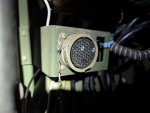
Looking over schematics, I realized that port P and S, marked in white in the picture, connects directly to C7 solenoid. (a easy way to check for other things from this port)
I measured the resistance and I had 2.9 ohms. Resistance measured at solenoid directly is 3.6 ohms. So wire harness resistance is 15 ohms. This looks right to me but, can anyone check please what value they have in their good working order central diff lock?
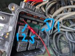
I also connected the c7 solenoid directly from wire 125 and D1 in VIM (picure), with no change.
this tells me that wiring is good.
thank you for any input.
 

Attachments

AdiBarbu

New member
18
7
3
Location
BC , Canada
The book you want is the MD3070 troubleshooting guide. Google "TS2470EN" and you can find it online for download as a .PDF

Like General mentioned a weak connection in the harness could be limiting the current delivered down to that C7 solenoid. pulls in with the peak signal but relaxes with the hold signal. This would appear as a brief pressure pulse on your gauge when mode is selected, same as the brief front driveshaft movement you have noted...
Thank you.
 

AdiBarbu

New member
18
7
3
Location
BC , Canada
No pressure at the test port either means the solenoid is bad or it's not being activated correctly. (Or you really don't have pressure but since the truck drives that seems unlikely). The small movement you are seeing could be the "peak" from the peak and hold PWM signal from the TCU and the solenoid isn't holding once the duty cycle/voltage drops off or it could indicate a poor connection in the circuit that is causing a voltage drop.

If you use an incandescent test light in series with the solenoid you could safety activate the coil without fear of burning it up. Just need something inline to limit current.
makes sense. thank you.
 

GeneralDisorder

Well-known member
Steel Soldiers Supporter
2,127
5,410
113
Location
Portland, OR
I'm not following how the resistance could be *lower* measured through the harness versus directly at the solenoid. The wiring should not be able to lower the resistance reading.

And resistance measurements (with a DMM for example) are not really appropriate for measuring the circuit resistance since the extremely tiny current being produced by the meter isn't enough to really load the circuit so there's really two problems:

1. Circuit resistance CANNOT drop when adding wiring to a resistive load. Logically those readings HAVE to be wrong or those aren't actually the same circuit or something. I'm not familiar with the pinout of the A0 diagnostic port so I would have to look that up to verify but I suspect something is wrong with the test procedure.

2. DMM resistance measurements using it's built-in 9v source aren't appropriate for checking the circuit. Better to isolate the circuit and do a load test with a known resistive load like an incandescent bulb - a high beam headlight bulb @ 12v can pull about 4 amps. If the wiring can light a bulb brightly then it's likely ok. The DMM can't test the ability of the circuit to actually drive a load so any resistance measurements are basically useless.
 

Ronmar

Well-known member
3,934
7,624
113
Location
Port angeles wa
Looking over schematics, I realized that port P and S, marked in white in the picture, connects directly to C7 solenoid. (a easy way to check for other things from this port)
I measured the resistance and I had 2.9 ohms. Resistance measured at solenoid directly is 3.6 ohms. So wire harness resistance is 15 ohms. This looks right to me but, can anyone check please what value they have in their good working order central diff lock?
I also connected the c7 solenoid directly from wire 125 and D1 in VIM (picure), with no change.
this tells me that wiring is good.
thank you for any input.
looks like you took a wrong turn somewhere… Lets start with the first pic. That large connector just inside the drivers door is the STE connector, stands for Standardized Test Equipment. It has NO connections whatsoever to the transmission wiring! The two pins you circled in white(P and S) connect to the starter and to the aux start solenoid respectively. Their intent was to either monitor the function of those components or allow control of them with a special test box plugged to that connector. STE really does not do much and any basically competent tech would quickly outgrow it. You can remove that connector, and the two black boxes just forward of it. They connect into the main truck wiring with 2 connectors tucked up into the dash. I can send you a pic later, pulled mine off years ago, and have re-used some of its wiring for other purposes…

The second pic, wire 125 has nothing to do with C7. In fact, unless you have a 6 wheel truck(3 axles) it is not even used.
A whole sequence happens when you go into 4X4

1. On the A0 you press mode, the trans controller, TCU selects a 5th gear preselect limit and the TCU outputs a mode indicator signal to the VIM on wire 114.
2. 114 energizes SF01 in the VIM.
3. SF01 in the VIM connects WIRE 161 and 163 sending a 4x4 request to the TCU which engages C7 to go from AWD to 4X4.
4. in 4X4 the TCU outputs a 4X4 indicator signal on wire 125 Back to the VIM. They programmed the TCU so that signal is reverse logic, so that 4X4 indicator signal actually de-energizes relay SF04 in the vim.
5. SF-04 in the vim is used to control 24v to an air solenoid under the passenger dash placed alongside the fan control air solenoid. That air feeds down to the rear middle axle on a 6X truck to lock up another center differential called a power divider so y0u can get torque applied to all 3 axles for maximum pull

there are no places in the transmission wiring to “sample” any of the transmission solenoid signals.

On the A0, the TCU in the drivers dash has 2 plugs on the back of it. One cable runs to the VIM, the other cable runs down to the transmission.

the cable running down to the transmission has an intermediary connector thru the front of the engine tunnel just forward of the gas pedal. You can reach it by removing the grill. That cable has some small branches that run to the front input speed sensor and also down to the C7/output speed connector on the transfer case, with the main branch of the cable ending at a connector down on the passenger side of the transmission above the valve body…
 
Last edited:

GeneralDisorder

Well-known member
Steel Soldiers Supporter
2,127
5,410
113
Location
Portland, OR
the cable running down to the transmission has an intermediary connector thru the front of the engine tunnel just forward of the gas pedal. You can reach it by removing the grill. That cable has some small branches that run to the front input speed sensor and also down to the C7/output speed connector on the transfer case, with the main branch of the cable ending at a connector down on the passenger side of the transmission above the valve body…
I've seen the bulkhead transmission harness connector incorrectly pinned from the factory - either the truck came that way or the ladies at the Motorpool swapped in a replacement harness that was pinned incorrectly.

Also apparently that area is prone to wire insulation degradation and transmission wiring circuits can short to each other in unpredictable ways. If the TCU signal for the C7 solenoid was partially shorted it could shunt the PWM signal to somewhere it's not supposed to go and that would probably render the solenoid weak and unable to stay pulled in and might ultimately damage the driver in the TCU.

At this point I would just put an oscilloscope on the C7 signal and see what is actually going on with it.
 

AdiBarbu

New member
18
7
3
Location
BC , Canada
thank you Ron and GD. I had that very wrong. Should I delete the post so no other people get confused?
After the post, I disconnected the solenoid and I had same readings hihi, so I realized I was way off. And yes, a wire only should add more resistance.
I will check the harness for any rubbing and do the bulb test as I don't have an oscilloscope. Cheap oscilloscopes over amazon would do it?
 

AdiBarbu

New member
18
7
3
Location
BC , Canada
also, what I find strange, is that even on black ice with all 4 wheels, there is no front wheel spinning. I mean 30% for front axle, in AWD, still there should be a front wheel spin on such low traction conditions. or not?
 

Ronmar

Well-known member
3,934
7,624
113
Location
Port angeles wa
also, what I find strange, is that even on black ice with all 4 wheels, there is no front wheel spinning. I mean 30% for front axle, in AWD, still there should be a front wheel spin on such low traction conditions. or not?
Is a rear wheel spinning? You only get 30% of the torque out the front if the center diff has something to push against. If a rear wheel is spinning under the conditions you describe, then 100% of the torque is escaping thru that spinning rear wheel. That is one reason for the standard 70/30 torque split typically found in AWD vehicles. It is easier to control a vehicle with a rear wheel spinning/sliding than a front…

park on ice, set the park brake and put it in drive and try again, that or jack up a front wheel and with the park brake set put it in drive. You should see 100% of the torque escape thru the front wheel that can slip or is lifted...
 
Top
AdBlock Detected

We get it, advertisements are annoying!

Sure, ad-blocking software does a great job at blocking ads, but it also blocks useful features of our website like our supporting vendors. Their ads help keep Steel Soldiers going. Please consider disabling your ad blockers for the site. Thanks!

I've Disabled AdBlock
No Thanks