• Steel Soldiers now has a few new forums, read more about it at: New Munitions Forums!

  • Microsoft MSN, Live, Hotmail, Outlook email users may not be receiving emails. We are working to resolve this issue. Please add support@steelsoldiers.com to your trusted contacts.

"Universal" Wiring for MEP002 and 003

CNGsaves

New member
8
0
0
Location
Kansas
So if I've got this right, powering "camper" setup would be wired particular way on MEP-002a lugs running in 120v 1 ph mode to get all the capacity of MEP-002a (ie thru 30A cord 120v to camper)? Curious if this could handle running say 13,000 Btu A/C in camper (along with other uses in camper on 12v inverted power) for extended periods?

Then when MEP-002a needed to serve as whole house backup, it'd be wired differently on MEP-002a lugs and ran in 120/240v mode and feed house (ie with interlock or transfer switch) with proper sturdy cord with say pin & collar plug on house? This would "self balance" the MEP-002a so it could be loaded with whatever it could handle by just selecting breakers in house that were necessities (ie house breaker panel either interlocked or thru a transfer switch)?

Finally, in "stand-a-lone" mode where MEP-002a is by itself sitting out in yard/boonies (with it's own grounding rod) then it'd be ran in 120/240v 1 ph mode and best way to utilize in this method would be install electric breaker box that had various plugs to take advantage of both 120v and 240v . . . right?

Anyway to make the transitions from these 3 uses of MEP-002a as easy as possible?

P.S. Any benefit of newer 5 Kw unit like say MEP-802a over the old reliable MEP-002a? I'm torn between which genset best for me, but appears that MEP-802a's have enclosure so maybe quieter? Ground rod needed in setup for long periods of use with camper?
 
Last edited:

edgephoto

Member
133
1
18
Location
Stafford, CT
So if I've got this right, powering "camper" setup would be wired particular way on MEP-002a lugs running in 120v 1 ph mode to get all the capacity of MEP-002a (ie thru 30A cord 120v to camper)? Curious if this could handle running say 13,000 Btu A/C in camper (along with other uses in camper on 12v inverted power) for extended periods?

Then when MEP-002a needed to serve as whole house backup, it'd be wired differently on MEP-002a lugs and ran in 120/240v mode and feed house (ie with interlock or transfer switch) with proper sturdy cord with say pin & collar plug on house? This would "self balance" the MEP-002a so it could be loaded with whatever it could handle by just selecting breakers in house that were necessities (ie house breaker panel either interlocked or thru a transfer switch)?

Finally, in "stand-a-lone" mode where MEP-002a is by itself sitting out in yard/boonies (with it's own grounding rod) then it'd be ran in 120/240v 1 ph mode and best way to utilize in this method would be install electric breaker box that had various plugs to take advantage of both 120v and 240v . . . right?

Anyway to make the transitions from these 3 uses of MEP-002a as easy as possible?

P.S. Any benefit of newer 5 Kw unit like say MEP-802a over the old reliable MEP-002a? I'm torn between which genset best for me, but appears that MEP-802a's have enclosure so maybe quieter? Ground rod needed in setup for long periods of use with camper?
For the camper you will need a ground rod. When connected to your house you do not want to connect to a ground rod. However you need to connect the ground lead in the cord connected to your house to the frame of the Generator.

The MEP-002A vs. MEP-802a has been discussed in several other threads. General consensus is the 802 is much quieter due to enclosure and engine design. You can buy an enclosure kit for the 002. The 802 is water cooled so there is more possibilities for failures. Obviously more maintenance. People also seem to feel parts are harder to come by for the 802s. Certainly a lot less used parts for the 802s now. The fuel consumption is a bit less with the 802.
 

edgephoto

Member
133
1
18
Location
Stafford, CT
A ground rod for the house is not required but a good idea
Actually it is not a good idea. Unless you ground the generator to the same ground tat your main panel is grounded to. This is the same reason you do not bond neutral and ground in a sub panel. There should only be one path to ground.
 

Crawdaddy

Member
444
4
18
Location
Louisiana
I think part of the confusion, at least on my part, is that the TM says to not load the phases with more than a 5% variation, but I think they also mean legs in 120/240v mode. If you refer to the diagram of how the coils in the genhead are wired together in various configurations, it's plausible to load them unevenly and cause problems. This can make versatile wiring of these sets difficult at best depending on what they really mean. Since the military seems to primarily deal in 3-phase, I think they really do mean phases. Who knows.

My potential loads have changed some. It will still be used for powering my camper with a 30 amp RV plug, but I will also be using it to tie into the house with 120/240. So, My plans are to hook up a short pigtail to the lugs with a L14-50 twistlock or similar connector. I'll keep the set in 120/240 mode. Then use that to feed another cord that ties into the house for house backup power use. For powering the camper and other loads, I'll use a breaker panel fed by the twistlock to break out the power to a 30 amp RV plug, a set of 15 amp receptacles for general use spread between breakers on opposite legs, and potentially other outlets as I think of them.

I think this configuration will work provided I can get away with the potential for having just the 25-30 amps of my camper on one leg of the generator in 120/240 mode. Grounding and neutral bonding to the frame will still have to be handled manually though.
 

LuckyDog

Member
394
11
18
Location
Freedom, NH
Here is what I did.

The schematic and TM says "When selecting position 120V, 1 PH unit is in 2 wire conf iguration. A situation can/may exist in allowing a double fault to occur. To eliminate this possibility the reconnection switch will be rewired by using an AWG #4 wire jumper between terminals #LO and #6 of section g(sic)." Should read Section 9. See my post below...

On the 002A I used a #8 to jumper between the terminals on the reconnection switch. (Crawdaddy's pic sort've shows this mod installed) With the correct guage jumpwer wire, you wouln't need to change the wiring on the luggs when switching between 120 single phase and 120/240 split phase. Lo is Low always. With the CORRECT guage jumper wire, LO can handle the full current in 120 single phase. (See: http://www.coonerwire.com/amp-chart/ No derating neccessary since this jumper is a single wire in free air (Instrumentation wiring) - If I am incorrect, someone please chime in) The wires from the lugs (L0,L1,L2,L,3) to the reconnection switch on my 002A are #4AWG.

What my plan is: I am going to build / buy an outlet/distribution box to attache permanently to my 002A. I will put indicator lights on the box to show which legs are live. (sort of like was done on Navy ship power panels) If I am in 120 single phase mode, only one lamp will be lit - and only those outlets in that section will be live. If I am in 120/240 split phase mode - two indicators will be lit and outlets in both sections will be live. Could do the same for 3-phase but I don't have any equipment like that (yet).

The danger (thing to be concerened about): IF a 240 load is connected to the box, and I am in 120 single phase, the load (equipment) will only be powered on one leg. (L1 = L0 = 0vac) So, you need to be careful, but don't need to rewire when you change the reconnection switch.

THIS WILL ONLY WORK IF THE JUMPER IS INSTALLED CORRECTLY.
 
Last edited:

Crawdaddy

Member
444
4
18
Location
Louisiana
Lucky,
Pictures of your mod?
Jerry
Yes, please show some pics of this mod. I didn't realize the hand-drawn L0 in the diagram for 120 mode illustrated the 120V only mode mod in the TM. That's just how I got the TM off the net. If what you said and what I understand is indeed correct, than there is a way to "universally" wire up the generator for most loads regardless of being in 120 only or 120/240 mode without worry of killing anything.

L3 in my distribution panel would get a majority of the receptacles and the 30 amp RV plug, and L1 would get a couple receptacles and things that run off 240 being laid across L1 and L3. A little thought would have to be put into how much load is being put on what receptacle when in 120/240 mode to ensure the load isn't grossly unbalanced, but I don't think it would be difficult.
 

LuckyDog

Member
394
11
18
Location
Freedom, NH
The 120V jumper mod for 002A and 003A

I did the jumper mod (X6A8 to L0) mentioned in the TM.
Jumper Schematic.jpg
I didn't take pictures while doing it.:-( Sorry. So, at Jerry's request, I came home and pulled the panel to try and get some pics.

When I did the mod, I removed the screws holding the plate with the lugs. I was then able to just lift it enough out-of-the-way. That is a must do. There just isn't enough room in there.aua

Again, on my 002A I used 8AWG wire. The manual states 4AWG. I do NOT recomend anything less than 4AWG for the 003A. This mod hard wires the L0 lug to terminal 6 on the switch (see Table 6.5 & Figure 6-10(.1 or .2) Switch Assembly, Rotary in the -34 manual if you want more information) On MY 002A with the type insulation of the wire I used, I can handle 65Amps without undue temperature concerns. Some wire insulations cannot handle high temperatures.

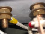
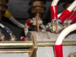
Here is the #4AWWG wire that connects to the L1
DSCN0497.jpg
Hard to see but it is labled X18A4 (the last digits ,just one in this case is the guage of the wire)

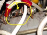
Here is the L0 jumpers.
L0 tabs.jpg
Found near the top of S6, near the left end. There are three of them here. They are copper and mine were bent on a little of an angle. I had to remove a washer to make room for the ring terminal. That's one end.
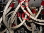
Now the other
x6A8.jpg
This is on the bottom. I circled the ring terminal I installed and the X6A8 wire. The wires marked 3 and 12 are jumper wires. Theres a bunch of them in there.

Becareful not to connect the jumper to X5 it is very close to X6 (and a lot easier to work on too.)
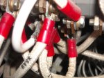
DSCN0496.jpg

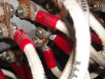
and two more views inside
DSCN0500.jpgDSCN0495.jpg


REMEMBER:::
IF you use L0 for a return/neutral instead of L1 in 120 single phase mode, ALL the current will run through the jumper before splitting up to generator leads 1, 6, 7, 12.

Select your wire size appropriately.

Did some more thinking and looking in the schematics.... Please see post below.
 
Last edited:

LuckyDog

Member
394
11
18
Location
Freedom, NH
So, I did some more thinking and research in the manuals. Looking at the different wiring diagrams.

Sorry, ran out of time.
Will finish work on the images. Then post.

Just quickly, I am comfortable with using L0 on MY MEP-002A for the neutral leg. I know my current usage. There is a risk of burning up the contact of the switch in section nine. I don't know what the contact rating is.

I am concerned that since most of the jumper inside the control box are #8 AWG, that the MEP-003A should not use the L0 as neutral. USE L1 for neutral. The jumper from L0 to 6 is just for grounding safety.

L0 also connects (bonding) to frame ground at the back of the ground lug under the control cubicle. This has to be set correctly for your use / situation.

Guess one size doesn't fit all, and there is no such thing as universal.
 

Crawdaddy

Member
444
4
18
Location
Louisiana
That's some interesting info to chew on LuckyDog. On one hand, I can't see the military instructing soldiers how to do it in the TM if they didn't think that jumper config could handle the stress and it wouldn't work to leave that jumper in there in all configs (120, 120/240, 120/208 Y). On the other, it's always possible.

In a bit of craziness and non-code compliance, I could put a breaker in the circuit breaker panel with heavy gauge wire that could tie L1 to L0 and put a huge warning label on it that the breaker should only be turned on in 120V only mode.

The L0 to frame bond is something that I can't think of a workaround for. Putting any sort of switch inline could potentially mean that the switch fails and the bonding is no longer there which is dangerous. A knife switch would be the most reliable and most visible switch to indicate what state it's in.
 
Last edited:

LuckyDog

Member
394
11
18
Location
Freedom, NH
I'm back with the promised images.

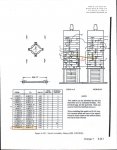
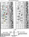
To complicate matters, there are two different switches used for the reconnection switch. Same part numbers basically but one ends with an "A" and the other a "B". Mine is an "B", so I highlighted the figures for my configuration.
Fig 6-10_100001.jpg20121205-00400001.jpg
The jumper is 6 inches of #8 AWG and I show where it is suppose to go. The wire is the same size on the "A" switch. It just connects on section 10 instead of section 9.

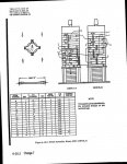
Table 6-50000100001.jpg
So, I took the information from figure 6-10.1 and drew a bunch of colored lines on table 6-5.
These are all those jumpers I mentioned earlier. They are ALL #8 except for the wire between section 14 & 17.

Here is my concern: The wire from L1 lug on the connection panel to the L1 (brown) lines is #4AWG. If the wire (X14A4) connects to section 4, then all current from L1 lug will split evenly between T1, T6, T7, & T12 (See figure 2-3 of the -12 or the figure in the OP) in the 120V single phase configuration.

If the all the current is passed through L0 lug, then ALL the current must go through the #8AWG wire to section 1, through the switch, then it can start dividing up among T1, T7, & 12. (Follow the red line)

If switch section one fails, then all the current will try to go through T6. Which wouldn't last long in that situation.

Roughly, 8AWG can carry 65 amps and 4AWG can carry 125 amps: WHEN in free air. Must derate for temperature and number of wires in a cable or conduit.

The 002A is rated for 52 amps, but the 003A is rated at 104 amps in the 120V single phase. When the current is split (properly) between the four windings (poles?), 8AWG is very safe in the control box for either generator. Trying to run the full current through an 8 AWG is sketchy in an 002A but unsafe in an 003A.

I do recomend putting the L0 to 6 mod in the control box with #8 wire. It gives you added safety and is the path to the ground lug in the 120V single phase configuration.

I do not recomend using the L0 as the grounding leg (neutral).

As for the bonding issue: I have considered using a battery disconnect switch. That would make bonding or not-bonding (L0 to gnd) the neutral easy. I haven't looked up what the AC current rating might be on a battery switch. They are designed for a lot of DC current and IF all is working correctly, there shouldn't be any current through the switch.

I do like the knife switch idea. Simple (big plus for me), visual, and reliable. Where would I find one rated for say 65 amps?

IF frogs had wings, they wouldn't bump their butts everytime they jumped either.
 
Last edited:

Crawdaddy

Member
444
4
18
Location
Louisiana
The TM states on Page 2-6 to use 4AWG to make that mod, which if it can carry 125 amps would satisfy the current carrying capacity of the jumper. I wouldn't think derating would come into play in this situation for proximity to other wiring because the wires are all helter-skelter in the reconnection box and not bundled close like they would be in conduit; derating due to temperature is another matter entirely. Then it becomes a question of whether the reconnection switch can handle all 104 amps across that terminal. That I don't know. Frankly, the reconnection switch is voodoo to me.
 

LuckyDog

Member
394
11
18
Location
Freedom, NH
The TM states on Page 2-6 to use 4AWG to make that mod, ...
I saw that statement too. That is partly why I did all that researching for doing mine. The TM mod has you connecting a 4AWG to an 8AWG that is already there. That #8 was hard enough to bend and fit in there. A #4 would be even harder and the #8 that you are connecting to would/could act like a fuse.

Instrumentation wiring like in the control box, doesn't really need derating. BUT the wiring in the control cubicle and between the box and cubicle does need derating because of the bundling.
 

aczlan

Member
79
1
8
Location
Upstate, NY, USA
Actually it is not a good idea. Unless you ground the generator to the same ground tat your main panel is grounded to. This is the same reason you do not bond neutral and ground in a sub panel. There should only be one path to ground.
Why not use BOTH a ground back to the main panel and one to a local ground rod?

Aaron Z
 

2icee

New member
2
0
0
Location
palmdale/California
Just recently acquired an mep 002a gen set. Came without a distribution box. Need to know how to get one or what are my options? Can it be test ran to see if it is working (Mechanically or electrically) without the distribution box. Would appreciate any help in getting this unit up and running.
 

Munchies

Member
417
3
18
Location
Keesler Air force base/ MS
Just recently acquired an mep 002a gen set. Came without a distribution box. Need to know how to get one or what are my options? Can it be test ran to see if it is working (Mechanically or electrically) without the distribution box. Would appreciate any help in getting this unit up and running.

I would post this as a new thread, and then people can respond there, and you can ask more questions on the same subject.
 
Top
AdBlock Detected

We get it, advertisements are annoying!

Sure, ad-blocking software does a great job at blocking ads, but it also blocks useful features of our website like our supporting vendors. Their ads help keep Steel Soldiers going. Please consider disabling your ad blockers for the site. Thanks!

I've Disabled AdBlock
No Thanks