• Steel Soldiers now has a few new forums, read more about it at: New Munitions Forums!

  • Microsoft MSN, Live, Hotmail, Outlook email users may not be receiving emails. We are working to resolve this issue. Please add support@steelsoldiers.com to your trusted contacts.

Wait light troubleshooting

jkcondrey

Active member
Steel Soldiers Supporter
317
141
43
Location
Rutherfordton, NC
Engine starts, runs great. Wait light does not come on. I have been following the troubleshooter in the TM and got to the point of testing voltage to the light itself. Troubleshooter states check for voltage on wire 27. I only get 6 volts at the wire. Trbstr does not state what voltage should be present. At least I have not seen the voltage listed yet. If that is the required voltage, Ill continue on. Does anyone know? I am going to pull both wires and try getting light off a spare battery but assumed it would need 12, but most suppliers I have seen mention that this is a light is an led and may only need a smaller voltage amount to work. Just didn't want to go further on the troubleshooter without getting another opinion.
 

Action

Well-known member
3,576
1,557
113
Location
East Tennessee
If you are following the flowcharts in the TMs, there are lines that run to the right of the flowcharts (from each step). Go to the next page and rear for more details. It tells the reason for each step and may give the proper volts.
the lines i described make more sense when you have the real paper book in front of you. The lines run from left page to right page.
 

Milcommoguy

Well-known member
Supporting Vendor
1,710
2,265
113
Location
Rosamond, CA
Engine starts, runs great. Wait light does not come on. I have been following the troubleshooter in the TM and got to the point of testing voltage to the light itself. Troubleshooter states check for voltage on wire 27. I only get 6 volts at the wire. Trbstr does not state what voltage should be present. At least I have not seen the voltage listed yet. If that is the required voltage, Ill continue on. Does anyone know? I am going to pull both wires and try getting light off a spare battery but assumed it would need 12, but most suppliers I have seen mention that this is a light is an led and may only need a smaller voltage amount to work. Just didn't want to go further on the troubleshooter without getting another opinion.

The wait indicator is an LED with a internal 300 ohm current limiting resistor. Wire # 27 is 24 volts from the "RUN" position. The other wire #571 is pulled low (to ground) in the "control box" to illuminate. They can and do go bad. Easy test. Ground the #571 lead to test with IGN switch in "RUN"

Control box, Smart start, EESS, PCB, etc. Not a fan, CAMO
 
Last edited:

jkcondrey

Active member
Steel Soldiers Supporter
317
141
43
Location
Rutherfordton, NC
The wait indicator is an LED with a internal 300 current limiting resistor. Wire # 27 is 24 volts from the "RUN" position. The other wire #571 is pulled low (to ground) in the "control box" to illuminate. They can and do go bad. Easy test. Ground the #571 lead to test with IGN switch in "RUN"

Control box, Smart start, EESS, PCB, etc. Not a fan, CAMO
I will give that a try today after work. Thanks!
 

jkcondrey

Active member
Steel Soldiers Supporter
317
141
43
Location
Rutherfordton, NC
Well if I followed the trouble shooter correctly, looks like its the sending unit not returning power to the light. Light was pulled and tested, works fine. Continuity out to the temp sender was good, but not in the sender. Ordered it last night.
 

Bulldogger

Well-known member
Steel Soldiers Supporter
1,330
586
113
Location
Quantico VA
Glad it was simple. Usually is. Please post the part number(s) used, in case someone else finds this thread later and has the same problem. Easy to do when it's on your mind.
BDGR
 

Milcommoguy

Well-known member
Supporting Vendor
1,710
2,265
113
Location
Rosamond, CA
Engine starts, runs great. Wait light does not come on. I have been following the troubleshooter in the TM and got to the point of testing voltage to the light itself. Troubleshooter states check for voltage on wire 27. I only get 6 volts at the wire. Trbstr does not state what voltage should be present. At least I have not seen the voltage listed yet. If that is the required voltage, Ill continue on. Does anyone know?
I am going to pull both wires and try getting light off a spare battery but assumed it would need 12, but most suppliers I have seen mention that this is a light is an led and may only need a smaller voltage amount to work. Just didn't want to go further on the troubleshooter without getting another opinion.
My response to the part in blue in post # 3 copied here.
The wait indicator is an LED with a internal 300 ohm current limiting resistor. Wire # 27 is 24 volts from the "RUN" position. The other wire #571 is pulled low (to ground) in the "control box" to illuminate. They can and do go bad. Easy test. Ground the #571 lead to test with IGN switch in "RUN"

This will test the LED only. That to me appeared to be the question. It is controlled by the "BOX" and it's CPU / timers and external sender "TSU"

Assumptions in yellow, can be faulty when working with the unknown. Still leading me to believe OP was experiencing an LED indicator fail as written.
For my time and trouble, I pulled the prints and followed the connections. Silly me.

Yes, there is a lot going on with the "Smart Box" to control the wait LED. IMO... WAY more complicated to glow cycle and start a truck. It could have been as simple as a very warm day with engine not needing a glow and wait OR most anything associated with this system.

It will be interesting to see what the fix is. I would almost say "disconnect the batteries... wait a minute or two, reconnect and check" That how scrambled up the "BOXES" can behave.

Anything is possible, even with the prints and TM's, CAMO Good LUCK.
 

jkcondrey

Active member
Steel Soldiers Supporter
317
141
43
Location
Rutherfordton, NC
My response to the part in blue in post # 3 copied here.
The wait indicator is an LED with a internal 300 ohm current limiting resistor. Wire # 27 is 24 volts from the "RUN" position. The other wire #571 is pulled low (to ground) in the "control box" to illuminate. They can and do go bad. Easy test. Ground the #571 lead to test with IGN switch in "RUN"

This will test the LED only. That to me appeared to be the question. It is controlled by the "BOX" and it's CPU / timers and external sender "TSU"

Assumptions in yellow, can be faulty when working with the unknown. Still leading me to believe OP was experiencing an LED indicator fail as written.
For my time and trouble, I pulled the prints and followed the connections. Silly me.

Yes, there is a lot going on with the "Smart Box" to control the wait LED. IMO... WAY more complicated to glow cycle and start a truck. It could have been as simple as a very warm day with engine not needing a glow and wait OR most anything associated with this system.

It will be interesting to see what the fix is. I would almost say "disconnect the batteries... wait a minute or two, reconnect and check" That how scrambled up the "BOXES" can behave.

Anything is possible, even with the prints and TM's, CAMO Good LUCK.
I appreciate the help CAMO. I was hoping it was just the light itself in all honesty. Funny thing is, when i went to pull the wires for the light, they had literally been plugged into one another lol. The other two connectors from the harness were zipped up and just dangling. So I did connect it up normal first and got nothing. I followed that troubleshooter as well as I could, but it looks like the sender is the issue(per the stopping point in the troubleshooter.) I ordered the part, so when it gets here I will replace it and see if that cures it. I will post back up then. Part out of Cali so it will be mid next week before I can try.
 

Milcommoguy

Well-known member
Supporting Vendor
1,710
2,265
113
Location
Rosamond, CA
I appreciate the help CAMO. I was hoping it was just the light itself in all honesty. Funny thing is, when i went to pull the wires for the light, they had literally been plugged into one another lol. The other two connectors from the harness were zipped up and just dangling. So I did connect it up normal first and got nothing. I followed that troubleshooter as well as I could, but it looks like the sender is the issue(per the stopping point in the troubleshooter.) I ordered the part, so when it gets here I will replace it and see if that cures it. I will post back up then. Part out of Cali so it will be mid next week before I can try.
Don't mine trying to help via interweb here on the SS Site. 🆘

Preliminary investigation of all the simple stuff is a good way to get a feel of what you got and what were trying to do or fix. So the fact is... it never did / could work. That would have been helpful up front. LED is just to let operator "WAIT" and let the glow plugs & controller do their thing. Might be why truck starts just fine.

So here we have a truck with a gremlin that unplugs wires and ty-raps others. I hope I never get one of those in my rig. LOL

Honestly, nothing funny here, CAMO
 

jkcondrey

Active member
Steel Soldiers Supporter
317
141
43
Location
Rutherfordton, NC
Well got the TSU today. Did not change the situation. Wait light does not illuminate. Back to the troubleshooter I guess. I may try to ground the 571 to the block and see if that changes it.
 

Milcommoguy

Well-known member
Supporting Vendor
1,710
2,265
113
Location
Rosamond, CA
Well got the TSU today. Did not change the situation. Wait light does not illuminate. Back to the troubleshooter I guess. I may try to ground the 571 to the block and see if that changes it.
If I follow... we know the LED is good on the bench, OK.

Do the test I recommended and follow along in the TM.

> https://www.stewartwarner.com/wp-content/uploads/2018/12/434956-Traditional-Electric-Gauge.pdf

Take a peek at page 440 shows basic connections to LED. Page 880 give "secret" overview of what is going in an OLD PCB. Not accurate for EESS or SMART boxes.

Check connectors "in and out" and get ready to spend big money. Disconnect batteries before work.

Over 800 pages of HumV fun, CAMO
 

jkcondrey

Active member
Steel Soldiers Supporter
317
141
43
Location
Rutherfordton, NC
Yeah I’m way into those 800 LOL at this point. I’m on page 2-318 of the -1 manual. Up to this point all checks fine. Again I only get 5 volts at the light so I think that wire 27 may be damaged someplace. I can’t see that 5 volts should be correct voltage. Getting dark out now so I’ll have to dig that tomorrow. The led tested fine on 12 volt battery outside of hmmwv, 5 doesn’t seem to be enough to light. But that 27f should feed more than 5 so we shall see if some squirrels or soldier B may have twisted or nicked it someplace.
 

Milcommoguy

Well-known member
Supporting Vendor
1,710
2,265
113
Location
Rosamond, CA
Yeah I’m way into those 800 LOL at this point. I’m on page 2-318 of the -1 manual. Up to this point all checks fine. Again I only get 5 volts at the light so I think that wire 27 may be damaged someplace. I can’t see that 5 volts should be correct voltage. Getting dark out now so I’ll have to dig that tomorrow. The led tested fine on 12 volt battery outside of hmmwv, 5 doesn’t seem to be enough to light. But that 27f should feed more than 5 so we shall see if some squirrels or soldier B may have twisted or nicked it someplace.
Check those pages (440 & 880) to see "to and from" circuit or pull the wiring diagrams and follow along. The 27 circuit feeds 24 Volts to all gauges... so the dash voltmeter could be a clue. Another... does the emergency / park "BRAKE" led work. It's on the same 27 circuit. Another clue if you follow my drift. Double check your meter against a known source... just in case of an operator induced error. aua

Lost ? Helps to have the road map, CAMO
 

jkcondrey

Active member
Steel Soldiers Supporter
317
141
43
Location
Rutherfordton, NC
I am at work looking at the schematic now. Looks like the 27 that feeds the wait light is a splice off the dash power. All gauges work correctly and come on, that part was covered in earlier step of the troubleshooter. Maybe the splice is bad. Guess I will follow it back through harness tonight.
 

M998-76’

New member
10
3
3
Location
Mooresville NC
Well got the TSU today. Did not change the situation. Wait light does not illuminate. Back to the troubleshooter I guess. I may try to ground the 571 to the block and see if that changes it.
I had the same issue with mine. I spent about 2 hours going through each connection and all grounds on mine this weekend. Turned the switch and BAM wait light works and volts draw down as intended. Your not far from me (im in Mooresville) if you where a little closer I would come by and give you a hand.
 

jkcondrey

Active member
Steel Soldiers Supporter
317
141
43
Location
Rutherfordton, NC
Yeah I was thinking about where that 27 would splice but maybe its on the back of the gauge panel and feeds to the others there as well. I guess I will find out tonight or tomorrow.
 

jkcondrey

Active member
Steel Soldiers Supporter
317
141
43
Location
Rutherfordton, NC
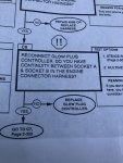
Alright back at it. So I ordered the original glow plug controller that was in the truck as well as the controller that is supposed to be the matching one for my Nartron box. Following the troubleshooter, 2-320, I do not have continuity between socket A and B on the harness. I tried both controllers and neither show continuity. Troubleshooter states replace controller. How likely is it to have 3 bad controllers, with 2 being brand new and the original that was on truck? 0DE9E3A9-D707-404F-95FB-C08C529A5A92.jpeg
My start box is Nartron 12469158-1 and I ordered 12469158-2 as well as the original sender that was on the truck.(not same part #).
 
Last edited:

Action

Well-known member
3,576
1,557
113
Location
East Tennessee
Alright back at it. So I ordered the original glow plug controller that was in the truck as well as the controller that is supposed to be the matching one for my Nartron box. Following the troubleshooter, 2-320, I do not have continuity between socket A and B on the harness. I tried both controllers and neither show continuity. Troubleshooter states replace controller. How likely is it to have 3 bad controllers, with 2 being brand new and the original that was on truck? View attachment 844266
My start box is Nartron 12469158-1 and I ordered 12469158-2 as well as the original sender that was on the truck.(not same part #).
Where exactly are you checking for continuity?
 

Action

Well-known member
3,576
1,557
113
Location
East Tennessee
S


Socket A & B in engine connector harness.
A is wire 54 that splits to 583 that ends up in pin 6 on the GPC or TSU.
B is wire 459 that runs to pin 3 on the GPC or TSU.

If you have no continuity between A and B on the end of the engine harness, Just unhook the GPC or TSU and check it for continuity between 3 and 6. If it works there but not at the end of the harness, a plug is not connected properly or the harness is messed up.
Or just try 3 and 6 on one of the GPC or TSU that is not in the truck.
 
Top