-
Steel Soldiers now has a few new forums, read more about it at: New Munitions Forums!
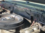
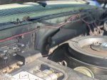
What the heck is it
- Thread starter Rrent
- Start date

More options
Who Replied?That's the 24 volt to 12 volt converter...if it's not hooked up then it's no big deal...it knocks 24 volt to 12 volt...I have one in the truck but the blazer one was removed long ago.Considering the cut wires on either side - I’m guessing it had something to do with the radio.
Yes, that metal thing behind the air cleaner. And yes (again) I know these wires need attention…View attachment 850844View attachment 850845
Sent from my SM-G955U using Tapatalk
cucvrus
Well-known member
- 11,478
- 10,507
- 113
- Location
- Jonestown Pennsylvania
In my opinion. I would hook it up. I ran these trucks for 27 + years with no adverse conditions or issues. It also helps pull the glow plug voltage from both batteries during cold start and reduces the strain and alternator on the front 12 volt battery and the Gen 1. I bought everyone I ever seen for sale because I read so much that they failed. Now I have a stack of complete resistors and after several hundred thousand miles and 100+ CUCV's I never had one fail. I had one get hot but that was a mouse nest on the back side. It smoked and burnt slightly and continued to operate as designed for years after. Do as you wish. But please repair that fusible link that is running to the 12 volt power point. Have a Great Day.
Once I remove the metal “plate/cover”. Will the repair be self evident? Is the fusible link anything special/different?In my opinion. I would hook it up. I ran these trucks for 27 + years with no adverse conditions or issues. It also helps pull the glow plug voltage from both batteries during cold start and reduces the strain and alternator on the front 12 volt battery and the Gen 1. I bought everyone I ever seen for sale because I read so much that they failed. Now I have a stack of complete resistors and after several hundred thousand miles and 100+ CUCV's I never had one fail. I had one get hot but that was a mouse nest on the back side. It smoked and burnt slightly and continued to operate as designed for years after. Do as you wish. But please repair that fusible link that is running to the 12 volt power point. Have a Great Day.
SomeNewGuy
Member
- 59
- 95
- 18
- Location
- VA
Once I remove the metal “plate/cover”. Will the repair be self evident? Is the fusible link anything special/different?
Fusible Links - 101
With all the electrical problems people are having with the CUCV starter and Glowplug systems lately, I thought I would post some info. -------------------------------------------------------------------------------------- This is from www.Whiteproducts.com. It is located in their FAQ section...
www.steelsoldiers.com
cucvrus
Well-known member
- 11,478
- 10,507
- 113
- Location
- Jonestown Pennsylvania
If you look closely you can see on the drivers side where someone cut the 10 gauge wire coming out of the resistors. I would remove the resistors and replace the wire and reattach it to the top post of the glow plug relay. The fusible link I am referring to is the poorly crimped yellow eye end that is on the main 12 volt power point connection. But I am being honest I never had any issues with any stock electrical configurations on a CUCV. Did I have things fail? Yes I would be a liar if I said differently. I just looked where the issue was that caused the failure and fixed that issue. I work on lots of cobbled up stuff and always repair hack jobs whenever possible. As many times as the TM's are referred to on this site I can't image the advise of hacking the systems. The originals worked for years and are about as simple as can be. Do as you wish. I like nice clean original vehicles. Good Luck. I still use the A C Delco 13G glow plugs and always will.
I’m pretty sure a 10 gauge as also cut from the passenger side.If you look closely you can see on the drivers side where someone cut the 10 gauge wire coming out of the resistors. I would remove the resistors and replace the wire and reattach it to the top post of the glow plug relay. The fusible link I am referring to is the poorly crimped yellow eye end that is on the main 12 volt power point connection. But I am being honest I never had any issues with any stock electrical configurations on a CUCV. Did I have things fail? Yes I would be a liar if I said differently. I just looked where the issue was that caused the failure and fixed that issue. I work on lots of cobbled up stuff and always repair hack jobs whenever possible. As many times as the TM's are referred to on this site I can't image the advise of hacking the systems. The originals worked for years and are about as simple as can be. Do as you wish. I like nice clean original vehicles. Good Luck. I still use the A C Delco 13G glow plugs and always will.
Is the fusible link anything special? If not, I’m guessing there is a size associated with it?
cucvrus
Well-known member
- 11,478
- 10,507
- 113
- Location
- Jonestown Pennsylvania
I buy the blue or orange fusible link and heat shrink a butt connector in the line at the end. But yes if both ends are cut both ends must be replaced. Good Luck.
MarcusOReallyus
Well-known member
- 4,524
- 820
- 113
- Location
- Virginia
Once I remove the metal “plate/cover”. Will the repair be self evident? Is the fusible link anything special/different?
Look up the "Helpful Threads" sticky at the top of the forum. Scroll down and you'll find a couple of threads which tell you how to remove it. Just reverse the steps.
Or not....
The circuit is simpler without it. It drops the 24v down to 12v which is then fed to the GPs. This confuses a lot of people, as you only see the drop when the GPs are actually operating. So, a lot of people remove it. It's not a trouble spot, though. It's really hard to burn out those resistors. It has been known to happen, but not often.
It works either way. /shrug/
Looks like 24 volt on the passenger side and 12 volt to the gp solenoid on the driver’s. Fusible links?If you look closely you can see on the drivers side where someone cut the 10 gauge wire coming out of the resistors. I would remove the resistors and replace the wire and reattach it to the top post of the glow plug relay. The fusible link I am referring to is the poorly crimped yellow eye end that is on the main 12 volt power point connection. But I am being honest I never had any issues with any stock electrical configurations on a CUCV. Did I have things fail? Yes I would be a liar if I said differently. I just looked where the issue was that caused the failure and fixed that issue. I work on lots of cobbled up stuff and always repair hack jobs whenever possible. As many times as the TM's are referred to on this site I can't image the advise of hacking the systems. The originals worked for years and are about as simple as can be. Do as you wish. I like nice clean original vehicles. Good Luck. I still use the A C Delco 13G glow plugs and always will.
Looks like 24v on the passenger side and 12v to the gp solenoid?Look up the "Helpful Threads" sticky at the top of the forum. Scroll down and you'll find a couple of threads which tell you how to remove it. Just reverse the steps.
Or not....
The circuit is simpler without it. It drops the 24v down to 12v which is then fed to the GPs. This confuses a lot of people, as you only see the drop when the GPs are actually operating. So, a lot of people remove it. It's not a trouble spot, though. It's really hard to burn out those resistors. It has been known to happen, but not often.
It works either way. /shrug/
MarcusOReallyus
Well-known member
- 4,524
- 820
- 113
- Location
- Virginia
Hey, since you are new to CUCVs, I'd say leave it alone unless things aren't working. Get to know the beast, fix any actual problems you have (this ain't one), and later you can decide if you want to mess with it.
It's no big deal either way.
It's no big deal either way.
MarcusOReallyus
Well-known member
- 4,524
- 820
- 113
- Location
- Virginia
Yes, sort of. If you have the stock setup, and your GPs are NOT engaged (turned on), you will see 24v all the way to the top of the GP resistor. When the GPs are engaged, you'll see 12v on the driver side if everything is working correctly.Looks like 24v on the passenger side and 12v to the gp solenoid?
If any of your GPs are fried, you'll see somewhere between 24v and 12v on the driver's side, depending on how many resistors are fried.
With the resistor bypassed, it's 12v all the way across whether your GPs are good nor not.
Please read the sticky on how it works before you decide to "fix" this.
I hear that - it will definitely be somewhere down on my to-do list. Looks like parasitic battery drain might well have shot to the top of that list - but, that’s a tomorrow thing,Yes, sort of. If you have the stock setup, and your GPs are NOT engaged (turned on), you will see 24v all the way to the top of the GP resistor. When the GPs are engaged, you'll see 12v on the driver side if everything is working correctly.
If any of your GPs are fried, you'll see somewhere between 24v and 12v on the driver's side, depending on how many resistors are fried.
With the resistor bypassed, it's 12v all the way across whether your GPs are good nor not.
Please read the sticky on how it works before you decide to "fix" this.
- 114,404members
- 167,297threads
- 2,355,030posts
- 2,302online users


