• Steel Soldiers now has a few new forums, read more about it at: New Munitions Forums!

  • Microsoft MSN, Live, Hotmail, Outlook email users may not be receiving emails. We are working to resolve this issue. Please add support@steelsoldiers.com to your trusted contacts.

Wheel Covers / Rim Protectors

Third From Texas

Well-known member
2,777
6,529
113
Location
Corpus Christi Texas
Ideally, you would want standoffs that sit against the rim, so they take the forces, not your bolts. You can use that coupler nut to extend the rim bolt to retain the rim protector. (Coupler nut indicated by thin orange square in this drawing.)
View attachment 802066
Agreed.

A small piece of tube that butts up against protector is the ideal. You could simply slip a sleeve over the coupling or just tack a small peice of tube to the outboard end of the coupling.

I looked all over for a round tube that was threaded 5/8 inside but couldn't locate anything. Then one day in Lowes I saw a big coupling and it hit me. We discussed it a bunch over on the lmtf FB group. Credit goes to someone else for finding the right coupling (this is his image but I forgot to label the author).

In any event, it's a very inexpensive solution for attaching the wheel cover/protector.
 

Third From Texas

Well-known member
2,777
6,529
113
Location
Corpus Christi Texas
yep.... IMHO this is easiest design. In off road world this would be similar to what they call a "rock ring" they fell out of favor pretty quick though cause mud packed up inside them. Maybe why they saw little use in the FMTV's??
I've been told that mud was a huge pita with the wheel covers (but I've yet to get in anything but sand with them).

IMO, a flat "ring" with openings around the edge, wide open in the center, and ample stand-off won't hold much if any mud. Remember, these only have to cover the air hoses and the CTIS.
 

Reworked LMTV

Expedition Campers Limited, LLC
Supporting Vendor
1,511
1,178
113
Location
TN
Can't do stamping, but can do flat disks. Flat disks I can cut in the next month or so. I'm very busy. My cnc plasma table is not dialed in yet. Need dimensions. prefer in DXF file format.

If someone provides .dxf file with dimensions, I will cut you a deal when I make them. Pun intended lol Ha!
 

Attachments

72
60
18
Location
Seattle Wa
So 12 gauge thickness is what they are made of then....
So if I could get the height and the below measurements we can CAD this and either waterjet or lathe out a die for the press.
If someone can get these to me I have time to play at my buddy's machine shop tomorrow, would be a fun deal...wheel protect.jpeg.jpg
 

Third From Texas

Well-known member
2,777
6,529
113
Location
Corpus Christi Texas
Well, the four holes for the stand offs are wheel bolts.

You're going to need a few more dimensions than that, though (unless you were to just be cutting flat discs).

You need cover depth, angles inboard and outboard where it folds down back into the rim, the counter-sink at the stand off holes, the location of the inner cut out for the hose (the OEM are correct the new CTIS but I seem to recall they were off center for the old style).

Someone up-thread posted the correction for the face/surface "oval-sorta hole".

And the small round hole doesn't line up with the manual inflation valve.

Ideally, you would sit down with and OEM cover and a rim l;eave nothing to chance.
*I know you were looking for one for this reason
 

Third From Texas

Well-known member
2,777
6,529
113
Location
Corpus Christi Texas
Had the opp to make a die to stamp these with yesterday... I may have another opportunity late this month or next it anyone can get me the above dimensions, that would be awesome.... thanks again guys...
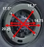
Sure, but as I said up thread...this is *not* enough info to do a die. You need several additional dimensions to make the cover.

The only important number that you requested in the center-to-center of the standoff bolt locations. You *absolutely* should double check this by simply measuring center-to-center of the *actual* wheel bolts (that the stand-offs screw down over). I would not go by what me Home Depot measuring tape says...

Good luck

wheel protect.jpeg.jpg
 

Third From Texas

Well-known member
2,777
6,529
113
Location
Corpus Christi Texas
Measuring on a spare in the garage gets me the same 17.5" but again, just using a tape.

And again, you really need to have one of these to look at or the CAD files.
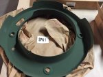
  • The stand-off bolts are counter-sunk into the face
  • One section of the inside wall is cut out to allow for the air lines
  • There are four sections of the outer wall cut out
  • There is a hole in the face for the manual inflation valve (incorrectly placed on the OEM cover)
  • And there is a cut out in the face for access to the CTIS (incorrectly placed on the OEM cover)
  • The side walls (inboard and outboard) are at an angle, not a 45° bend

Image from page 1 of this thread:

IMG_0695.jpg
 
Top
AdBlock Detected

We get it, advertisements are annoying!

Sure, ad-blocking software does a great job at blocking ads, but it also blocks useful features of our website like our supporting vendors. Their ads help keep Steel Soldiers going. Please consider disabling your ad blockers for the site. Thanks!

I've Disabled AdBlock
No Thanks