• Steel Soldiers now has a few new forums, read more about it at: New Munitions Forums!

  • Microsoft MSN, Live, Hotmail, Outlook email users may not be receiving emails. We are working to resolve this issue. Please add support@steelsoldiers.com to your trusted contacts.

Winch install question/issue

Guruman

Not so new member
Steel Soldiers Supporter
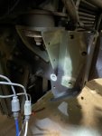
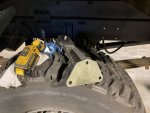
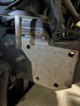
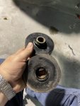
So. I've been slowly working to get my winch installed. This week I've been chipping away at the front roller assembly. I already had the bumper off to pound out a kink from an errant stump, so removing the handful of bolts from the old cab mount was pretty easy. A 30mm socket removed the bushing nut without much drama. Even the bushing does not look too bad. Win-win.

I installed the new roller assembly/cab mount, and other than needing to go back and run the cab lift a few times to get the upper bushing back in, no big deal. All in all it was less than an hour of working.

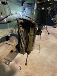
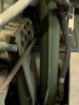
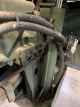
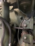
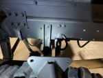
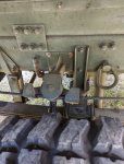
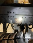
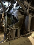
Now that it's back together. I have no idea how this is supposed to work. The cab lift cylinder is directly in line with he cable path from the newly installed roller assembly.

Did the winch trucks have a different lift mechanism? or different lift cylinder position/bracket? What am I missing here?
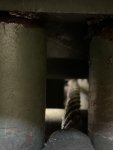
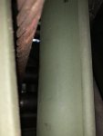
IMG_2235.jpg
IMG_2236.jpg
IMG_2237.jpg
IMG_2234.jpg
IMG_2238.jpg
 

Guruman

Not so new member
Steel Soldiers Supporter
Isn’t there a stand-off bracket?
I'm not seeing a standoff bracket in the pic.

If there is...

A) This is the first I'm hearing of it.

B) I don't have it.

Unless you're talking about the little pulley on a stick that helps route the cable, in which case I do not see how that will help. I think the lift mechanism needs moved outboard a few inches.
 

Lostchain

Well-known member
Steel Soldiers Supporter
285
587
93
Location
Portland, OR
On my factory winch truck, I noticed that the cable path is really close to the lift cylinder, I think they are depending on the cable routing roller on the frame to keep the cable from rubbing on the cylinder too much.

BAD84971-5A1C-42E9-9C84-C39811D79B78.jpegAF0AE285-F70C-4749-801E-F836E1FB326E.jpeg69DEE324-3E80-4090-999E-3EC7E87EFFF0.jpeg

You can see on the below pic how close the cable is to the hydraulic lift cylinder. Less than an inch. But in practice, as there is tension applied to the line, the frame mounted roller is pulling the line away from the cylinder back towards the frame.


1E3B239C-BE3A-4559-9623-765F41402E12.jpeg
 

Lostchain

Well-known member
Steel Soldiers Supporter
285
587
93
Location
Portland, OR
Wow, that's close. Seems to me that if the cable is taught against that outboard roller, it'll be scuffing the lift cylinder... maybe not. Thanks for the pics @Lostchain

Yeah I worried about that myself, but I think it would be light if it happens at all. Not sure how much the winch was used by the soldiers but the cylinder has only the lightest of scuffing as you can see on this pic. You have to zoom in to see it there on the inboard side of the cylinder.

74528BFD-8E87-4AA3-94BE-A90909B09304.jpeg
 

Ronmar

Well-known member
3,845
7,474
113
Location
Port angeles wa
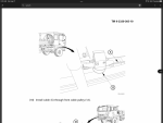
Yea there should be a roller guide back by the shock above the leaf springs that holds the cable in close to the frame at that point to guide it up thru that narrow gap between cab lift and frame structure…

CC8DBBB9-3F45-4767-9F9B-0D12B79A3625.png
 

Guruman

Not so new member
Steel Soldiers Supporter
So. I was missing the front guide roller, but I have it now.

That means that the one I've been looking at must be the rear one. It has three mounting holes.

I do not have matching holes anywhere near where I think it should go.

For others who have done this before, did you have to drill new holes in the frame for this? Ideally don't want to have to drill any without a mag drill.

IMG_2258.jpgIMG_2257.jpg
 

Guruman

Not so new member
Steel Soldiers Supporter
Hahaha, I’ve got the same issue. I looked at the trucks at work, 6 wheel units, they have a guide like that but a square mount on the frame side. I’ll be waiting for replies too.
Well I do have a 4-hole pattern right where I think this should go.... I might have to lop off this three hole flange and fabricate a 4-hole to match the existing frame holes. Not sure if that's easier than drilling three new holes in the heat treated frame or not..... Maybe an adapter plate?
 

Wingnut13

Well-known member
235
562
93
Location
Strafford, NH
Well I do have a 4-hole pattern right where I think this should go.... I might have to lop off this three hole flange and fabricate a 4-hole to match the existing frame holes. Not sure if that's easier than drilling three new holes in the heat treated frame or not..... Maybe an adapter plate?
I’ve been thinking the same thing. Just hadn’t got to it yet. I was thinking I’d find out where it really is supposed to go in the meantime.
 

Guruman

Not so new member
Steel Soldiers Supporter
Looking at yours again, it appears the cable runs on the inside of the pulley.
Sorry. My pulley in the pic is not completely assembled. There is a "batwing" metal guide to keep the cable in contact with the pulley, I just don't have it all together. I didn't mean to confuse anyone.

I was more worried about the mismatched bolt holes in the frame.

I'm working to resolve that now...

IMG_2259.jpg
 

coachgeo

Well-known member
5,147
3,462
113
Location
North of Cincy OH
Looking at yours again, it appears the cable runs on the inside of the pulley.
Sorry. My pulley in the pic is not completely assembled. There is a "batwing" metal guide to keep the cable in contact with the pulley....
phewwww...... glad she's got the bat wings..... looking at it as an inside job like MrMikey was saying had me thinking this must not be FMTV related part at all... an inside jobby would mean you could not quick remove the cable for running winch out the opposite way.

run her and gun her.... (then pull winch it out)
 
Top