• Steel Soldiers now has a few new forums, read more about it at: New Munitions Forums!

  • Microsoft MSN, Live, Hotmail, Outlook email users may not be receiving emails. We are working to resolve this issue. Please add support@steelsoldiers.com to your trusted contacts.

goldneagle's 1985 M1008 recovery and restoration thread...

goldneagle

Well-known member
4,510
1,007
113
Location
Slidell, LA
If you go ORD, it will be a spring kit for the front with a steering block to correct the steering geometry. For the rear, it will be your option; either a block or a shackle reversal. If you are not going to off road much, I would go with the block because of cost and your load rating will not change. That Summit kit is quite the coin, but if you have it, go for it!
I need to call them tomorrow to see what the ORD kit will cost me. The Summit kit had the shocks and Pittman arm included.
 

goldneagle

Well-known member
4,510
1,007
113
Location
Slidell, LA
Today was a nice day out so I decided to start working on the Tachometer hookup. I set up some wires with a 5 amp fuse in-line and attached it to the 12 volt battery. I tapped into the single thin brown wire coming from the driver's side alternator. Hooked it tot he spade terminals on the tachometer. I set the micro switches to Off-On-Off which is 13-20 pulses per revolution.

When I started up the truck at fast idle i was reading 1100 RPM on the tach. When it dropped to idle it was reading about 700-750 RPM. Since I was not sure the actual IDLE RPM I did not mess with the fine adjustment.

I did some research tonight and found 650 +/- 25 RPM is normal. So i will need to fine tune the tach to the proper range before installing into the dash.

I wanted to share the info with those who might want to install their own tach. Mine is a VDO Cockpit International 4,000 RPM 2 1/16" (52mm) Tachometer, 12V #333 035 024X I got it for $40 shipped from a popular internet auction site.
 

goldneagle

Well-known member
4,510
1,007
113
Location
Slidell, LA
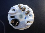
I did some calculations to determine if my micro switch settings were correct. What I determined is: Since my RPM readings are a little high and the micro switches are set for the highest pulses per revolution there is no way to lower the displayed RPM by choosing a lower Pulses per RPM -since that would make the viewed RPM even higher. So all i need to do is use the rheostat to fine tune the RPM to around <700 RPM. At least I am close to getting it done now!

Here is a back shot of the tachometer showing the micro switches settings.

Back_tach_1.jpg
 
Last edited:

goldneagle

Well-known member
4,510
1,007
113
Location
Slidell, LA
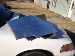
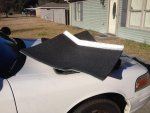
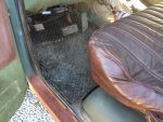
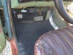
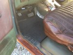
I received the polyethylene sheets I ordered last week. I cut the 1/2" thick one to fit under the floor mat in my truck. I glued some thin heat/sound insulation to the back of it.

Floor_Insulation_1a.jpgFloor_Insulation_1.jpg I did the same for the passenger side.

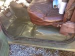
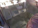
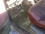
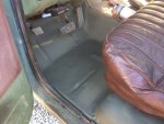
I used Acetone to clean the floor pan on the driver's side. I then applied a good coat of Rusty Metal Primer. I then applied 2 coats of Rustoleum Green CAMO paint.

M1008_floor_1c.jpgM1008_floor_1b.jpgM1008_floor_1a.jpgM1008_floor_1.jpgM1008_floor_2.jpg

Once dry I installed the padding and floor mat.
 

goldneagle

Well-known member
4,510
1,007
113
Location
Slidell, LA
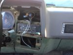
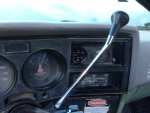
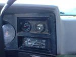
Today I decided to install the tachometer into the dash. I drilled a 2" hole next to the charging meter. I then used a Dremel tool to slightly enlarge it to allow the tachometer to fit. I then reconnected the tachometer temporarily to be able to fine tune the setting to approximately 650+/- 25 RPM. All it took was a slight turn of the adjustment screw to get it set.

When I took apart the dash I noticed the positive line to the light bulb on the charging indicator was not attached. It had broken off at the tiny brass contact inside the lamp holder. I purchased a spare lamp holder and borrowed one of the brass contact and wire. It fit perfectly into the old lamp holder. I wired the 2 gauges with wire leads and connectors attached in order to make it easier to remove the dash at a later date. I used insulated male and female spade connectors.

I ran 2 Teflon coated wires from the engine compartment to the instrument panel to attach to the tachometer. One wire was spliced into the brown wire on the alternator and the 2nd went temporarily to the POS on the battery. (Fused line) I wanted to test the tachometer before I buttoned-down the dashboard. I still have to find a source of 12 volts that is off when the ignition key is off. I also need to Ty-wrap the wire under the hood.

Started up the truck and the tachometer pointed to the 1000+ RPMs cold. Later it dropped to normal idle and read about 650+/- 25 Rpm. I finished screwing together the dashboard. The light also comes on in the tachometer when the headlight lever is pulled out.

Here are some pictures of the work:
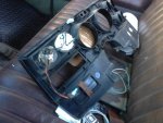

Tach_1.jpgTach_1a.jpgTach_1b.jpgTach_1c.jpg
 

cpf240

Active member
1,479
5
38
Location
Free in Northern Idaho
Is the housing of that tach isolated from its ground? Otherwise, the voltmeter might be "on" all the time, as it is the ground connection to it that is switched by the 24v relay, and its mounting bracket, etc, is isolated from the metal parts of the dash, etc.
 

goldneagle

Well-known member
4,510
1,007
113
Location
Slidell, LA
Is the housing of that tach isolated from its ground? Otherwise, the voltmeter might be "on" all the time, as it is the ground connection to it that is switched by the 24v relay, and its mounting bracket, etc, is isolated from the metal parts of the dash, etc.
The housing on the tachometer is all plastic. There are 2 ground locations. One for the instrument light and one for the tach. The original installer of the voltmeter tapped into the ground feeding the voltmeter to also power the - ground of the lamp on the unit. There is a separate hot (positive) that feeds that lamp. I shared the negative ground from the lamp on the voltmeter to power the lamp and tach on the tachometer. I also shared the positive from the lamp on the voltmeter to the positive on the lamp on the tachometer. I still have to find a positive feed for the main positive on the tachometer.
 

cpf240

Active member
1,479
5
38
Location
Free in Northern Idaho
There are open spots in the fuse box that are 12v hot when the key is on, a spade terminal will fit in there. I'm using one to power the 12v accessory socket I put in the ash tray. There is at least one spot in the fuse box that is 24v, as I recall, so check first!
 

goldneagle

Well-known member
4,510
1,007
113
Location
Slidell, LA
There are open spots in the fuse box that are 12v hot when the key is on, a spade terminal will fit in there. I'm using one to power the 12v accessory socket I put in the ash tray. There is at least one spot in the fuse box that is 24v, as I recall, so check first!
I am glad you mentioned about some of the locations on the fuse block are 24 volt. I used my lighted tester to find live connection points in the fuse box. I could tell if they were 12 or 24 volt by the brightness of the tester. Found a 12 volt source that was only on when the ignition switch was on. Used a flat spade terminal to plug into it. I installed a 5 amp inline fuse to protect the circuit. Ty-wrapped the wires under the dash and under the hood. Job completed. Now I have a working tachometer in the dash.
 

goldneagle

Well-known member
4,510
1,007
113
Location
Slidell, LA
Now that I had the dash cover off I know what part I need to repair the shift indicator. I ordered a new one from a seller on Ebay. It arrived this weekend. Been busy with other tasks so I have not installed it yet. Just need to figure where the clip attaches to on the steering column.

I also purchased new strike bolts for the door locks. These bolts catch the door lock when you shut the doors. They were worn and missing the vinyl sleeves. Was an easy replacement. Door close much nicer now. Tachometer still functions perfectly.
 

Whitfield

Member
116
5
18
Location
Richmond Virginia
Good work ~ Thanks for sharing the tach information. Your truck will be like new before too long.

Restoring the shift indicator is next on my to do list. I'll be searching those TM's later this week. It looks like a complicated cable / pulley set up using the weak dash plastic a a mount for the change of direction.
 

goldneagle

Well-known member
4,510
1,007
113
Location
Slidell, LA
Good work ~ Thanks for sharing the tach information. Your truck will be like new before too long.

Restoring the shift indicator is next on my to do list. I'll be searching those TM's later this week. It looks like a complicated cable / pulley set up using the weak dash plastic a a mount for the change of direction.
I did mine today. The pulley was broken off. i used a self tapping screw with a nylon bushing as a replacement pulley point. Unfortunately I cracked the plastic dash where it goes around the the steering column. Will do a custom repair on that spot.
 

goldneagle

Well-known member
4,510
1,007
113
Location
Slidell, LA
Update on gear indicator (pointer) repair. Removed the self tapping screw. Installed a shorter bushing and reinstalled screw. Used Gorilla Tape from underside of plastic dash to secure broken pieces to dash. Dash reinstalled properly now. Gear indicator still works.
 

goldneagle

Well-known member
4,510
1,007
113
Location
Slidell, LA
I have been having hard starting issues with the truck. Been using the glow plugs as supposed to. Sometimes it takes 4 attempts of cranking to get her started. Starter runs great! I think it's the glow plugs. Have not had a chance to test them. I read in another thread they should read 1 to 3 ohms if good. I decided to order some new ones anyway since they are only $9.09 each with free shipping from AMAZON. They should arrive on Friday.

Just a note: The truck does seem to start on first attempt on some warm days. The leak in the IP could also be a possible reason for a hard start. (assuming the leak allows air into the IP when the truck is sitting)
 

goldneagle

Well-known member
4,510
1,007
113
Location
Slidell, LA
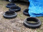
Got a great deal on some HMMWV tires and rims for the truck. Brand new 37" Goodyears. I got 5 HMMWV rims with damaged tires still on them. I spent yesterday taking the rims off the tires. It was quite a struggle but I got them all done! I asked a friend on suggestions of how to pull the run-flats from the tires so I could reuse them with the new tires. He suggested cutting the side walls with a jigsaw and bi-metal blade. It only took about 15 minutes to cut 5 tires and remove the the run-flats. Later I scrubbed the run-flats clean for re-installation. I ordered some run-flat lube kits for the reinstall. They come with 2 tubes of lube, new o-ring and new nuts for the rims.

Here are some pictures of the run-flats and tires cut open:


Run_flats_1.jpgRun_flats_1a.jpg


I am also planning on fabricating a swinging tire mount that attaches to the rear bumper to hold the HMMWV spare tire. It will swing out of the way to allow the tailgate to drop down.
 
Last edited:
Top
AdBlock Detected

We get it, advertisements are annoying!

Sure, ad-blocking software does a great job at blocking ads, but it also blocks useful features of our website like our supporting vendors. Their ads help keep Steel Soldiers going. Please consider disabling your ad blockers for the site. Thanks!

I've Disabled AdBlock
No Thanks