• Steel Soldiers now has a few new forums, read more about it at: New Munitions Forums!

  • Microsoft MSN, Live, Hotmail, Outlook email users may not be receiving emails. We are working to resolve this issue. Please add support@steelsoldiers.com to your trusted contacts.

FLU419 SEE HMMH HME Owners group

rtrask

Well-known member
342
251
63
Location
San Luis Valley, Colorado
The good news is the mog is again building air pressure. The bad news is that other than replacing the head gasket on the compressor (which I am no longer confident was the issue), I changed nothing and I am confident that there are other issues.
Perhaps it is just my reluctance for taking yes for an answer, but I have a sneaking suspicion the problem will recur.
Here are some possibilities.

  1. Replacing the head gasket on the mog compressor. (The reason I doubt this is that the pressure measured by a finger over the output line did not seem any better.) I think it is still possible that when the pressure got higher than little dutch boy sticking his finger in the dike it started leaking at the compressor gasket. if that were the case however, I think there would have been at least some pressure in the tanks.
  2. Charging the system from my shop compressor / quickly releasing that pressure by disconnecting the hose knocked whatever was blocking the pressure from getting to the tanks loose. ( The reason I doubt this is that in my first go round on this back in December, I did not find anything blocking pressure from the compressor to the jumble of connections at the tanks, and after I completed that process, there was still no air getting to the tanks. )
  3. Happy accident. While I had the shop compressor connected to the water drain valve, I noticed that air was leaking from the alcohol injector. I had a feeling at the time that perhaps this was due to pressure being introduced from the wrong side, but I had started up the mog, and at some point I heard that happy whoosh sound and a snap similar to when a tubeless tire seats but softer, and the air stopped leaking at the alcohol injector. My thought on that was that the pressure from the mog got higher than the pressure from the shop compressor and pushed one of the little rubber "O" rings into place. ( The reason I don't think it was this is that, is that this all started prior to me ever touching the alcohol injector.

Who knows? Maybe it was more than one / a combination of things.

Some other observations:
  1. The primary air circuit, and the trailer air circuit have one way valves which allow them to hold pressure independent of each other. I was able to install my compressor connection plug in each tank, and no air ever got into the supply circuit or the other tank.
  2. By sticking my compressor plug fitting into the drain valve I was able to fill both systems easily, but could hear no leaks except the one by the alcohol injector. (I missed that water drain valve when I replaced the ones in the tanks. and I am ordering a new one.
  3. There is no missing line that goes from the front glad hands back. When I looked in the parts catalog it only shows the line going to the booster. It is a smaller diameter line than I would have thought, but I don't think anything is missing.
  4. The trailer brake lines, what is there and what is missing is still a mystery to me, but at this point my care level is too low to resolve it.
  5. TM 5-2420-224-34 has the best information on working on the compressor. Student handbook is probably the clearest on describing the routing of the air lines of the two systems, and subsystem of the primary circuits
  6. I did not time how long it takes to get from zero pressure up to 105 PSI which is where it stops building for me, but I did time how long it take to get from 60 PSI to 105 PSI, and it took about 6 minutes.
  7. When at 105 PSI, it takes about 15 minutes for the pressure to drop down to 60 PSI.

If anyone has any data on how long it takes their system to build and drop pressure I would love to hear what your mog does. I do not think there is any problem with the compressor piston, rings, or the cylinder liner. I think I may order a kit that includes new valves. Cost of the kit is < 18$ US. I have posted additional info on this link https://www.steelsoldiers.com/showt...ference-XREF&p=2203046&viewfull=1#post2203046
 
Last edited:

The FLU farm

Well-known member
Steel Soldiers Supporter
3,341
1,328
113
Location
The actual midwest, NM.
There is no missing line that goes from the front glad hands back. When I looked in the parts catalog it only shows the line going to the booster. It is a smaller diameter line than I would have thought, but I don't think anything is missing.
If there's no missing line, you're obviously good.

But, the one you want to use wouldn't go to the brake booster - that sounds like the gladhand that activates the brakes as needed. The other one is used to supply air to the tanks and the one that is the ideal way to fill the tanks from an external source.

It's been a while since I had to start from 0, but as I recall it took maybe four to five minutes until the unloader valve popped, at about 600-700 rpm.

That it takes only 15 minutes for you to lose 45 psi sounds like a fairly meaningful leak to me. I'd think you'd be able to hear where that one is with relative ease.
The Winter SEE goes down to 60 psi in a month or two, the Summer SEE can drop to 30 in a week sometimes.
 

rtrask

Well-known member
342
251
63
Location
San Luis Valley, Colorado
If there's no missing line, you're obviously good.

But, the one you want to use wouldn't go to the brake booster - that sounds like the gladhand that activates the brakes as needed. The other one is used to supply air to the tanks and the one that is the ideal way to fill the tanks from an external source.
Well since mine is the only SEE I have ever seen, I don't know for sure what is there and what is missing except by diagrams in the manuals.

gladhand.jpg

Looking at that diagram, it does not look like there is a spot to connect the line going to the back to charge the system. The high level diagram showed a line going back to charge the system but there must be one so it must be missing. I knew logically the line going to the booster could not supply air to the system.
 
Last edited:

rtrask

Well-known member
342
251
63
Location
San Luis Valley, Colorado
I replaced the seals on my boom cylinders and now I can't get the boom to latch using the last second direction reversal to get it over center. I was able to get it to latch using the stabilizer pushing on the bucket, but I am not even close with the correct technique.

Any ideas as to what the problem is and is there any thing I can do to fix it?

I suspect that residual air could be trapped in one or both of the cylinders.If so will that self correct with usage?
 

The FLU farm

Well-known member
Steel Soldiers Supporter
3,341
1,328
113
Location
The actual midwest, NM.
Ron, just found this "auto saved" post which apparently never got anywhere.

Well, I can't say that I have traced the air lines back from the front gladhands to see where they go. I took for granted that they'd work just like on Class 8 trailers, and they do.

Also, I must admit that I lost track here. Didn't you say that one gladhand didn't have a line connected to it, yet air didn't come out anywhere when it was pressurized?
Either way, let's hope that someone here has the cab tilted on a FLU with an intact air system. That should be the easiest way to follow the line from gladhand to where it enters the air system.
Or, figure out where that number 31 valve is and run a line to it.
 

The FLU farm

Well-known member
Steel Soldiers Supporter
3,341
1,328
113
Location
The actual midwest, NM.
I replaced the seals on my boom cylinders and now I can't get the boom to latch using the last second direction reversal to get it over center. I was able to get it to latch using the stabilizer pushing on the bucket, but I am not even close with the correct technique.

Any ideas as to what the problem is and is there any thing I can do to fix it?

I suspect that residual air could be trapped in one or both of the cylinders.If so will that self correct with usage?
Funny you mention the latching, since yesterday I was a bit surprised over how nicely the Summer SEE latched - with me standing on the ground, reaching over to the lever, and the engine at about 800 rpm. It was completely smooth and practically noiseless.

Anyway, yes, you may need to work some air out of the system, by fully extending and contracting the boom a couple of times.
 

peakbagger

Well-known member
734
360
63
Location
northern nh
Mine does on occasion latch as intended but most of the time its a battle. i park it with the front end lower than the rear which occasionally helps but sometimes no choice but use the outrigger.
 

The FLU farm

Well-known member
Steel Soldiers Supporter
3,341
1,328
113
Location
The actual midwest, NM.
Maybe you're just trying to do it too fast? I know I did the first time, and it was violent.
I'd think that reversing the lever too late could be the main cause. And running high rpm could make it trickier, I suppose.
 

rtrask

Well-known member
342
251
63
Location
San Luis Valley, Colorado
Ron, just found this "auto saved" post which apparently never got anywhere.

Well, I can't say that I have traced the air lines back from the front gladhands to see where they go. I took for granted that they'd work just like on Class 8 trailers, and they do.

Also, I must admit that I lost track here. Didn't you say that one gladhand didn't have a line connected to it, yet air didn't come out anywhere when it was pressurized?
Either way, let's hope that someone here has the cab tilted on a FLU with an intact air system. That should be the easiest way to follow the line from gladhand to where it enters the air system.
Or, figure out where that number 31 valve is and run a line to it.
Well Like I said before, since my SEE is the only SEE I have seen I can only guess by the pictures in the TMs and what I see on my SEE so to speak. Enough double talk.

gladhand.jpg

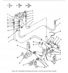
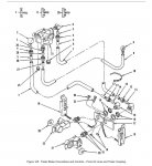
When I look at the connections to the front glad hands it looks exactly like the diagram above. The lines from both glad hands go up to and connect to that valve 31. From valve 31, there is one line which is a fairly small diameter (9) that connects to the brake booster. The diagram above does not show a line running to the back which would pressurize the tanks and the rest of the system. From an earlier post you said and I think you are correct that the small diameter line running to the brake booster is a control line that signals the booster to apply the brakes. It makes sense to me that there would be a line going to the back to pressurize the tanks etc., but on my SEE there is no evidence that such a line ever existed. Which is why I said there was no line missing.

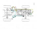
Perhaps that small diameter line (9 on the diagram) is what pressurizes the entire system but it seems unlikely to me, because then how would that small line also signal when to apply the brakes? Also the diagram below seems to indicate that there are two lines. The diagram below is just a schematic so it may not reflect reality. I believe that somehow when you and others connect pressure to the front glad hands you are getting pressure through out the system. Since pressure is now getting from the compressor to the tanks, and the pressure gauge on the dash, I could try again with the glad hand on the front to see if the air will move through the system now. When I connected a pressurized glad hands to either of the glad hands on the front before no air seemed to go anywhere. It did not show any pressure on the dash, and I did not hear any air moving through the system.

FluAirSystemHighlighted.jpg

You don't need to have the cab tilted to see the guts of the front glad hands. Just pop the hood and take a look at that valve (31) over by the either canister. If you are real ambitious you can get on the ground and see the plumbing from the glad hands going through the cab up to the valve. If there is a line that goes to the back of the system that is where I would expect it to tie in. It is just a mystery to me.
 

rtrask

Well-known member
342
251
63
Location
San Luis Valley, Colorado
Maybe you're just trying to do it too fast? I know I did the first time, and it was violent.
I'd think that reversing the lever too late could be the main cause. And running high rpm could make it trickier, I suppose.
Before I put the seal kits into my boom cylinders it just worked. I would bring it up and as soon as it started to slow down I would just reverse direction and it would move in position. Now it seems to stop moving toward me sooner than it did before, and reversing direction just sends it back down. After giving it a little boost from the stabilizer I can use the boom lever in the down direction to get it back far enough so the ring slips over the peg. I tried it with slow RPMs first and then switched to higher RPMs and it made no difference.

The reason I think it might be related to air in one or both cylinders is that it slows as it comes back and just kind of seems squishy if that makes sense.
 

The FLU farm

Well-known member
Steel Soldiers Supporter
3,341
1,328
113
Location
The actual midwest, NM.
When I connected a pressurized glad hands to either of the glad hands on the front before no air seemed to go anywhere. It did not show any pressure on the dash, and I did not hear any air moving through the system.
If your covers have been off for any amount of time, keep in mind that mud dobbers like to make their nests in places like that, effectively closing the air flow off.
 

rtrask

Well-known member
342
251
63
Location
San Luis Valley, Colorado
The covers were on when I got it, but who knows. The dobbers certainly plugged up 2 of the 7 brake bleeder valves.

I will check to make sure the air flows through.

Different topic, is there any use for the dipper rod I replaced? Boat anchor comes to mind, but if it has some value I would like to do something useful with it.
 

The FLU farm

Well-known member
Steel Soldiers Supporter
3,341
1,328
113
Location
The actual midwest, NM.
Different topic, is there any use for the dipper rod I replaced? Boat anchor comes to mind, but if it has some value I would like to do something useful with it.
That is good, straight steel. It can be used for all kinds of projects, so don't toss it.
Instead, bring it with you when you come here and study air lines and such.
 

rtrask

Well-known member
342
251
63
Location
San Luis Valley, Colorado
Help, my FLU 419 will not come out of low range on the gear box shifter? I have read the manual and it appears something is wrong. Does anyone have any ideas on where to Start?
Hi Skywagon,

To get some meaningful help you probably need to provide more details, I likely can't help but it would be the starting point for someone who might be able to. First off what do you mean when you say stuck in low range on the gear box shifter?

Here is a diagram for the shift levers from the operators manual.

shifters.jpg


From the operators manual

  1. Main Shift Lever (1). Shifts all speeds no matter what gear range or intermediate speeds are preselected.
  2. Intermediate Speed Control (2). Intermediate speeds are main transmission reduction speeds
  3. Group Shift Lever (3). The group shift selector has three shifting functions: Gear Range I-low group; Gear RangeII-high group; and R-reverse

What exactly is stuck? Is the clutch working? Does the transmission have oil in it? Was there any noise that proceeded the problem.

Here are some previous posts that might have helpful information in them.

https://www.steelsoldiers.com/showt...Owners-group&p=1833337&viewfull=1#post1833337
https://www.steelsoldiers.com/showt...Owners-group&p=1833455&viewfull=1#post1833455
https://www.steelsoldiers.com/showt...Owners-group&p=1933328&viewfull=1#post1933328
 
Last edited:

rtrask

Well-known member
342
251
63
Location
San Luis Valley, Colorado
Accelerator Linkage Adjustment

Has anyone had a problem with a runaway throttle on the SEE?
Last year I manufactured a throttle connecting rod because mine was so badly bent that I was afraid it's strength was compromised after I straightened it back out. I found the hand throttle also badly bent but fortunately correctable. While I was at it I installed all new springs for the throttle linkage. The hand throttle was still non functional, so I adjusted the throttle connecting rod following the procedure outlined in TM 5-2420-224-20-2 on pages 4-68 & 4-69

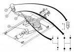
Even with the throttle linkage correctly adjusted I have found that if I pull the hand throttle back far enough the throttle will stick wide open and you can't get it unstuck while the dog house is on. What happens is that when the spring goes past vertical it acts to hold the throttle wide open rather than return it. You can see what I mean below:

ThrottleAdjustment.jpg

This seems like a design flaw to me, but maybe it just not a problem in practice because you would not pull the hand throttle back that far. I have not tried it with the engine running, and don't plan to but I have been thinking about putting some kind of limiter on to prevent it from happening. What do you all think?
 

Pinsandpitons

Active member
162
55
28
Location
Central Washington
My see has a little loop of wire attached to the injection pump side of the throttle linkage. It comes up through a small hole drilled in the cab just behind the doghouse. Functionally it serves as a kill switch the same as pushing the hand throttle all the way forward. Not sure why it’s there but its a good backup l think. When I first got my see i had a situation where the foot throttle locked at WOT somehow and i was able to save the day by pushing the hand throttle forward but if that didn’t work i was headed for that little wire. There was a clunk associated with the throttle getting stuck, even through the hand throttle fixed it I wonder if that was a similar situation as you described? Anyway, food for thought.
 

rtrask

Well-known member
342
251
63
Location
San Luis Valley, Colorado
My see has a little loop of wire attached to the injection pump side of the throttle linkage. It comes up through a small hole drilled in the cab just behind the doghouse. Functionally it serves as a kill switch the same as pushing the hand throttle all the way forward. Not sure why it’s there but its a good backup l think. When I first got my see i had a situation where the foot throttle locked at WOT somehow and i was able to save the day by pushing the hand throttle forward but if that didn’t work i was headed for that little wire. There was a clunk associated with the throttle getting stuck, even through the hand throttle fixed it I wonder if that was a similar situation as you described? Anyway, food for thought.
Thanks for the tip, that seems like a good solution. Maybe some piano wire or something like that. Thin and strong, that's not going to impact normal function with the added advantage of being able to pull it back if need be in an emergency. I haven't tried to floor it with the pedal to see if it could get into the stuck situation I described; I suspect not. It must have happened to some previous owner of your SEE though.
A
 

rtrask

Well-known member
342
251
63
Location
San Luis Valley, Colorado
Thanks for the tip, that seems like a good solution. Maybe some piano wire or something like that. Thin and strong, that's not going to impact normal function with the added advantage of being able to pull it back if need be in an emergency. I haven't tried to floor it with the pedal to see if it could get into the stuck situation I described; I suspect not. It must have happened to some previous owner of your SEE though.
I checked the accelerator pedal and it sticks wide open, and the hand throttle doesn't bring it back. I think am going to need to do more than just be able to pull it back when it sticks. I think I will still follow Pinsandpitons suggestion as an emergency remedy, but it would be too easy getit stuck wide open.There must be something wrong that I have not been able to spot. The length of the connecting rod I made is the same as the original and it is adjusted out as long as possible so that the hand throttle will stop the engine when all the way forward. In fact I have to go a little beyond the stop for the engine to die.

One idea I have is to drill a new hole in the bracket so the spring is closer to the engine block. I am afraid there will not be enough adjustment though. Maybe I need to manufacture a different bracket.This could be a very trial and error filled process.
 
Top
AdBlock Detected

We get it, advertisements are annoying!

Sure, ad-blocking software does a great job at blocking ads, but it also blocks useful features of our website like our supporting vendors. Their ads help keep Steel Soldiers going. Please consider disabling your ad blockers for the site. Thanks!

I've Disabled AdBlock
No Thanks