• Steel Soldiers now has a few new forums, read more about it at: New Munitions Forums!

  • Microsoft MSN, Live, Hotmail, Outlook email users may not be receiving emails. We are working to resolve this issue. Please add support@steelsoldiers.com to your trusted contacts.

FLU419 SEE HMMH HME Owners group

The FLU farm

Well-known member
Steel Soldiers Supporter
3,338
1,319
113
Location
The actual midwest, NM.
I would guess this is for our resident Case expert Speedwoble, but can anyone confirm if the rod for the bucket cylinder (part no G103351 from the TM... P2) is the same as part no G33162. I did a web search on the TM's part number and only out of stock on hits, but there is a lot of hits on the G33162 and it is supposed to fit Case 580B, 580C, 580D, 580E, and others.
Your local Case dealer probably has them. Give them the measurements to make sure it'll fit.
 

rtrask

Well-known member
342
251
63
Location
San Luis Valley, Colorado
I am back to trying to sort out the air lines. I pressurizing the system through a glad hand connected to the right rear trailer glad hand, but the air only went as far as the the valve (TM P-1 page 0167 00-3, Item 21 -- N-20949-CA VALVE,BRAKE PNEUMAT 4/2 WAY). Is there some trick to get it to pressurize the rest of the system or is the valve just faulty?

The Mog's air compressor is putting out some air, but it seems pretty anemic. I can hold my thumb over the output pipe through multiple compressor strokes. Is this normal?

I have a brief video, but no way to post it.
 

alpine44

Member
397
17
18
Location
Asheville, NC - Elkton, MD
I am back to trying to sort out the air lines. I pressurizing the system through a glad hand connected to the right rear trailer glad hand, but the air only went as far as the the valve (TM P-1 page 0167 00-3, Item 21 -- N-20949-CA VALVE,BRAKE PNEUMAT 4/2 WAY). Is there some trick to get it to pressurize the rest of the system or is the valve just faulty?

The Mog's air compressor is putting out some air, but it seems pretty anemic. I can hold my thumb over the output pipe through multiple compressor strokes. Is this normal?

I have a brief video, but no way to post it.
I think you have to pressurize through the front glad hand similar to when the FLU419 is being towed and supplied with air by the towing vehicle.
 

The FLU farm

Well-known member
Steel Soldiers Supporter
3,338
1,319
113
Location
The actual midwest, NM.
Yep, like Alpine pointed out, the rears are outlets, the fronts are inlets.

I think the FLU's compressor is anemic on a good day. Not that I know its specs, but with the limited tank volume it really should fill them much faster.
One of these years I'll probably install an electric compressor for the very few things that actually need air; the diffs.
 

rtrask

Well-known member
342
251
63
Location
San Luis Valley, Colorado
I think you have to pressurize through the front glad hand similar to when the FLU419 is being towed and supplied with air by the towing vehicle.
Yeah. I tried putting it on the front briefly, but heard no air movement through the system. When I tried to trace the lines at the front it looked like there was only a very small one leaving the valve. I will give it another shot. I currently have some lines disconnected back by the tanks so if air will flow from the front I should know right away.

The cylinder head on the compressor looks pretty beaten up around the nut by the outlet valve. I suspect that it has been repeatedly beaten on to free it up.


20190317_113507.jpg

There is a parts kit for it that seems to be readily available. I will try that to see if it makes a difference. Has anyone else had experience with that?
 

rtrask

Well-known member
342
251
63
Location
San Luis Valley, Colorado
I looked at the lines coming off the front glad hands and there is no line connecting the valve to the rest of the system. So the glad hand can't supply air to the system to diagnose a leak or blockage, but there is no blockage between the pump and the tank. So I think the pump is the most likely candidate.

The valves in the compressor head look good, but after looking at the head there is fair amount of corrosion around the head. I think that it is loosing pressure through the gaskets. I ordered a couple of new gaskets so hopefully that will do the trick.


20190317_210807.jpg
 

The FLU farm

Well-known member
Steel Soldiers Supporter
3,338
1,319
113
Location
The actual midwest, NM.
I looked at the lines coming off the front glad hands and there is no line connecting the valve to the rest of the system. So the glad hand can't supply air to the system to diagnose a leak or blockage...
Not that I think you'll normally use the front gladhands other than as an easy way to fill and troubleshoot the system, but if someone removed part of the air line, why not replace it?
 

rtrask

Well-known member
342
251
63
Location
San Luis Valley, Colorado
Not that I think you'll normally use the front gladhands other than as an easy way to fill and troubleshoot the system, but if someone removed part of the air line, why not replace it?
Seems like a lot of trouble / expense for no benefit. I have a different scheme for pressurizing the system to check for leaks that I will try after I get the pump back together. I bought a couple of the tank drain valves from EI a while back, because they were leaky. Not being one to throw anything away I kept the old ones. I have pulled the spring & check valve out of the worst one. I am going to drill and tap it to fit a regular 1/4" plug so I can just connect the hose from my compressor directly to the larger tank.
 

Speedwoble

Well-known member
606
301
63
Location
New Holland, PA
Seems like a lot of trouble / expense for no benefit. I have a different scheme for pressurizing the system to check for leaks that I will try after I get the pump back together. I bought a couple of the tank drain valves from EI a while back, because they were leaky. Not being one to throw anything away I kept the old ones. I have pulled the spring & check valve out of the worst one. I am going to drill and tap it to fit a regular 1/4" plug so I can just connect the hose from my compressor directly to the larger tank.
Good idea. Years of working on things have taught me to proceed very slowly when changing things. Since you are adding air in the reverse of the typical direction, I would add a regulator or a ball valve as a restrictor to allow you to adjust how fast the air comes into the tank. This way you don’t have a huge rush of air in reverse that knocks crud loose in the lines. Pro tip, put the ball valve at the air compressor so the noise is far away from where you are trying to troubleshoot. Starting with the valve almost closed, you can slowly open it.
 

911joeblow

Active member
508
68
28
Location
Utah
Since you have the pump apart, I put my head on a belt sander to clean it up. I know it's not a true surfacing job but I figured it would at least clean up any corrosion and make it seal up a bit better. I also cleaned up the valves and such. Works much better now. Still not great but after a new regulator and alcohol injector the system is great as long as I am patient in the morning to let it pump up.
 

The FLU farm

Well-known member
Steel Soldiers Supporter
3,338
1,319
113
Location
The actual midwest, NM.
Seems like a lot of trouble / expense for no benefit. I have a different scheme for pressurizing the system to check for leaks that I will try after I get the pump back together. I bought a couple of the tank drain valves from EI a while back, because they were leaky. Not being one to throw anything away I kept the old ones. I have pulled the spring & check valve out of the worst one. I am going to drill and tap it to fit a regular 1/4" plug so I can just connect the hose from my compressor directly to the larger tank.
I wouldn't say that replacing one measly air line is a lot of trouble, and it most certainly can't be labeled as expensive. Not even if buying the line from Grainger.
I also wouldn't say that having the front gladhands operational has no benefit.

Anyway, removing one of the (to me) useless factory air connectors and replacing it with a normal quick disconnect allows me to use the little air there is in the system for certain tasks, and it can obviously also be used to pressurize most of the system.
 

rtrask

Well-known member
342
251
63
Location
San Luis Valley, Colorado
Good idea. Years of working on things have taught me to proceed very slowly when changing things. Since you are adding air in the reverse of the typical direction, I would add a regulator or a ball valve as a restrictor to allow you to adjust how fast the air comes into the tank. This way you don’t have a huge rush of air in reverse that knocks crud loose in the lines. Pro tip, put the ball valve at the air compressor so the noise is far away from where you are trying to troubleshoot. Starting with the valve almost closed, you can slowly open it.
As an alternative, maybe I can just use the pressure regulator on the compressor to bring the pressure up in 20 PSI increments. rather than hit it with 100 PSI all at once.

It does not seem like I will be going backward through the system for very many components, All the schematic shows up stream of the tank are the pressure relief valve, the pressure regulator and the alcohol injector.

View attachment 758666
I will need to verify again, but I think the lines are OK from the compressor to the tank. I got some air coming from the compressor, and I was able to use a blow gun with a rubber tip to get air from where the source line from the compressor connected to inlet to the Alcohol injection system, through the pressure regulator and across to the pressure relief valve by the tanks. I believe the compressor is the problem because I was able to hold my thumb over the outlet pipe from the compressor for multiple compressor strokes. My theory at this point is that it is leaking from the compressor head gasket, and just can't build pressure. I ordered a couple of compressor head gaskets from Couch Off-Road Engineering that should get here today.

There is a .65 mm, and a .9 mm gasket. The TM does not specify which goes where, but I intend to put the .65 against the engine block and the .9 against the head.
 

rtrask

Well-known member
342
251
63
Location
San Luis Valley, Colorado
I wouldn't say that replacing one measly air line is a lot of trouble, and it most certainly can't be labeled as expensive. Not even if buying the line from Grainger.
I also wouldn't say that having the front gladhands operational has no benefit.
Perhaps it is not that expensive or that much trouble, and if I did not have a viable alternative I might do that, but for sure it is more expensive and bother than tapping my old drain valve and screwing in a quick connect plug. The other consideration is that I am not sure how much is missing. The lines that go into the anti jack knife lever are gone, and I am not sure what all is missing to make it operational.
View attachment 758672

But just curious what other benefit do you see in having them operational?


Anyway, removing one of the (to me) useless factory air connectors and replacing it with a normal quick disconnect allows me to use the little air there is in the system for certain tasks, and it can obviously also be used to pressurize most of the system.
Not sure if I fully get you here, are you suggesting I should put normal compressor connector in place of one of the factory ones? I like that idea, but will require dealing with conversion from metric to the standard fitting.
 
Last edited:

rtrask

Well-known member
342
251
63
Location
San Luis Valley, Colorado
Since you have the pump apart, I put my head on a belt sander to clean it up. I know it's not a true surfacing job but I figured it would at least clean up any corrosion and make it seal up a bit better. I also cleaned up the valves and such. Works much better now. Still not great but after a new regulator and alcohol injector the system is great as long as I am patient in the morning to let it pump up.
Thanks Joe I was intending to do something similar with some fine grit sand paper and steel wool. Since you have been through it, does the smaller thickness gasket go against the block?
 

The FLU farm

Well-known member
Steel Soldiers Supporter
3,338
1,319
113
Location
The actual midwest, NM.
Perhaps it is not that expensive or that much trouble, and if I did not have a viable alternative I might do that, but for sure it is more expensive and bother than tapping my old drain valve and screwing in a quick connect plug. The other consideration is that I am not sure how much is missing. The lines that go into the anti jack knife lever are gone, and I am not sure what all is missing to make it operational.
But just curious what other benefit do you see in having them operational?
Not sure if I fully get you here, are you suggesting I should put normal compressor connector in place of one of the factory ones? I like that idea, but will require dealing with conversion from metric to the standard fitting.
There's no need to make the entire trailer brake part of the system operational, just the air feed. It is one line.

Aside from a very convenient (and correct) way to put air into the system, that feed can be used if you ever get towed with a strap or chain, for example, want power assisted brakes and don't like using the clutch as a brake pedal. Or to put enough air in the system to make the 4WD and lockers work, if the machine is otherwise operational.

Conversion fittings may not be on the shelves at Pep Boys, but they exist in many, many places.

Overall, I think you're making what seems to be a minor issue a lot more complex than it needs to be. Get some pressure into the system whichever way you prefer, then listen for the leak(s).
If someone has removed much of the trailer brake system, I know where I'd start looking...um, listening.
 

Speedwoble

Well-known member
606
301
63
Location
New Holland, PA
I would guess this is for our resident Case expert Speedwoble, but can anyone confirm if the rod for the bucket cylinder (part no G103351 from the TM... P2) is the same as part no G33162. I did a web search on the TM's part number and only out of stock on hits, but there is a lot of hits on the G33162 and it is supposed to fit Case 580B, 580C, 580D, 580E, and others.
From what I can see, G103351 is a 2.5” diameter rod for the model 35C while G33162 is a 2” diameter rod and was used on the model 35 backhoe.No inventory of the 2.5” rod.

There was a special use cylinder G109713 with a 4” bore and 3” rod diameter. Could be a nice upgrade, but no stock available.
 

rtrask

Well-known member
342
251
63
Location
San Luis Valley, Colorado
There's no need to make the entire trailer brake part of the system operational, just the air feed. It is one line.
Aside from a very convenient (and correct) way to put air into the system, that feed can be used if you ever get towed with a strap or chain, for example, want power assisted brakes and don't like using the clutch as a brake pedal. Or to put enough air in the system to make the 4WD and lockers work, if the machine is otherwise operational.
OK, Still not convinced it is worth it personally because I don't own another vehicle that has air brakes, so probably not likely to get towed. As far as charging the system, If I put the female connector on in place of the factory one which is an idea I like I could do the same thing with a short hose that has the male plug on both ends. :deadhorse: I will stop beating this dead horse now.

Conversion fittings may not be on the shelves at Pep Boys, but they exist in many, many places.
Yeah, I know the fittings will not be that hard to put together, I was mostly asking to make sure that is what you were talking about. I currently down't have the metric to SAE hose fittings, but do have a connector plug, a drill and NPT tap and the old drain plug that is not doing me any good.. I will order the fittings because I think that is a real good idea.
Overall, I think you're making what seems to be a minor issue a lot more complex than it needs to be. Get some pressure into the system whichever way you prefer, then listen for the leak(s).
If someone has removed much of the trailer brake system, I know where I'd start looking...um, listening.
Well if I am making a big deal about it, it is because I made zero progress on it over the weekend. I tried connecting the glad hand to 3 of the 4 possibilities with no results except when I connected it to the back right glad hand and the check valve to prevent what I was trying was slowly leaking. Both front glad hands sealed well and the air went nowhere even when I had disconnected lines by the tanks.

When I first got the thing building up air was the only thing that worked well. So I don't think it is because of an incomplete job on removing the trailer / tow breaks.

Perhaps I am miss understanding or miss reading the diagram.
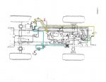
FluAirSystemHighlighted.jpg
View attachment 758688

What I have highlighted in Yellow is the line that I can't find. It is I believe missing and runs from the front to the back. The line I have highlighted in green is there, but it is a much smaller in diameter and I believe it is used to signal the brakes into action. The blue highlight just shows the normal path from the compressor to the tank. I really don't see that pressurizing the tank directly is much if any different from pressurizing it from the glad hand. I will take Speedwoble's advice and bring the pressure up slowly to avoid any damage.
 
Last edited:

The FLU farm

Well-known member
Steel Soldiers Supporter
3,338
1,319
113
Location
The actual midwest, NM.
OK, Still not convinced it is worth it personally because I don't own another vehicle that has air brakes, so probably not likely to get towed.
You don't need another vehicle with air brakes. I frequently move trailers (with air brakes) using whatever vehicle is suitable, and a portable air tank.

Although, for me, towing a FLU would be with a cobbled up tow bar anyway since I can't easily tow with a strap by myself, so no need for air.
 
Top