• Steel Soldiers now has a few new forums, read more about it at: New Munitions Forums!

  • Microsoft MSN, Live, Hotmail, Outlook email users may not be receiving emails. We are working to resolve this issue. Please add support@steelsoldiers.com to your trusted contacts.

MEP-004A, No output

peapvp

Well-known member
Steel Soldiers Supporter
1,115
1,229
113
Location
Basehor, KS
Wiring Diagram for the correct Hammond PH250MGJ as T2 replacement in A11

Ok folks,

here it is.

Math:

Original T2 Transfer Ratio:

208VAC to 128VAC = 1.625 : 1

Hammond PH250MGJ Tansfer Ratio:

387VAC to 240VAC = 1.6125 : 1

Maximum Output Current on Secondary side in this configuration: 1.04 Amps AC (twice of whats needed)

Note: a transformer does not care if you apply a lower Voltage on the primary, you will get exactly the transfer ratio on the output up to max current of the secondary - because this a CE rated transformer it is 387 instead of 380 even though it says it on the label.


Hammond T2 Replacement Wiring Diagram.jpg


And the PDF to download
 

Attachments

Last edited:

peapvp

Well-known member
Steel Soldiers Supporter
1,115
1,229
113
Location
Basehor, KS
Brian,

thank you - with the 45.5 VDC A11 in the gen - how much can you regulate the output voltage of the genset up and down with the front panel rheostat?


Peter,

I read your post just after I tested the board but thank you very much for the information.

I purchased this generator in 2012 and in 2013 it had an over voltage error but the generator
didn’t shut down. I documented the problems on this site at that time. I had corrosion on most of
the diodes. To repair it I sourced all the parts on the VR board including the connector and
stocked at least 1 of each just in case I needed them. (the connector was partially melted)
This is why I have so many parts.

To test parts that I suspect are affected by heat I put an ohm meter on them and heat them up.
I’m not sure it’s a normal test procedure but it works. I’m not worried about the value shown
during the test just how it reacts to the heat. I heated each part around U1 and was surprised
that most of the resistors never changed value. VR3 stayed solid and VR1 changed value a little.
When I heated CR9 the value changed up and down a lot. When it cooled it returned to normal.
I removed CR9 and checked it with the same results.
I only changed CR9 so I would know if that fixed it and it did.

The main reason I change all the caps is their age, to eliminate future cap problems and they are
inexpensive. I ran out of C6 caps though.

I then replaced VR1, VR3, R12 (it changed when heated) they are only a few cents and
easy to replace.

I get a solid 45.5 vdc instead of 48. I’m not sure if that is a problem but it is within 10%.

CR9 was one of the components I had trouble sourcing.
I replaced it with a 1N4002 but can’t remember how I got to this diode.

Brian
 

peapvp

Well-known member
Steel Soldiers Supporter
1,115
1,229
113
Location
Basehor, KS
Brian,

CR9 is not listed in the parts manual, but from the pic I got it starts with 1N and its a glass diode.

So, this maybe a 1N4148 or from the 1N41xx Series.

They change quite a bit with temperature - they are general purpose diodes for switching applications have a faster recovery time then the 1N40xx which are common rectifier diodes and can't handle the surge currents associated with switching.

Here is the datasheet:

View attachment 1N4148-1118184.pdf

Peter,

I read your post just after I tested the board but thank you very much for the information.

I purchased this generator in 2012 and in 2013 it had an over voltage error but the generator
didn’t shut down. I documented the problems on this site at that time. I had corrosion on most of
the diodes. To repair it I sourced all the parts on the VR board including the connector and
stocked at least 1 of each just in case I needed them. (the connector was partially melted)
This is why I have so many parts.

To test parts that I suspect are affected by heat I put an ohm meter on them and heat them up.
I’m not sure it’s a normal test procedure but it works. I’m not worried about the value shown
during the test just how it reacts to the heat. I heated each part around U1 and was surprised
that most of the resistors never changed value. VR3 stayed solid and VR1 changed value a little.
When I heated CR9 the value changed up and down a lot. When it cooled it returned to normal.
I removed CR9 and checked it with the same results.
I only changed CR9 so I would know if that fixed it and it did.

The main reason I change all the caps is their age, to eliminate future cap problems and they are
inexpensive. I ran out of C6 caps though.

I then replaced VR1, VR3, R12 (it changed when heated) they are only a few cents and
easy to replace.

I get a solid 45.5 vdc instead of 48. I’m not sure if that is a problem but it is within 10%.

CR9 was one of the components I had trouble sourcing.
I replaced it with a 1N4002 but can’t remember how I got to this diode.

Brian
 

flydude92

Member
117
9
18
Location
Waterville, Ohio
Brian,
I have one more suggestion for you. I don't know on how many DMM's you have available, but if possible, I would hook up one DMM in AC Range on T2 X1 and X3 and one on T2 H1 AC Current besides the output measurement in DC on J11 R/S when testing VR Boards.
You can use the known good VR as reference for this - On X1 / X3 you should measure ~ 128VAC +/- 4VAC with 208VAC on H1 / H2 (this transformer business is not an exact science...)
With your original T2 the X1 / X3 AC Voltage should not drop by more then 4 VAC with a good VR Board and a good C2
If it it does, then this will indicate issues with C2 and/or the VR Board - if this Voltage is within +/- 4 VAC then the entire lower DC Voltage on J1 R/S is solely coming from the VR Board
Would be interesting if you could share your results here! Thanks Peter
I will try it and let you know.

Brian
 

flydude92

Member
117
9
18
Location
Waterville, Ohio
Brian,
CR9 is not listed in the parts manual, but from the pic I got it starts with 1N and its a glass diode.
So, this maybe a 1N4148 or from the 1N41xx Series.
They change quite a bit with temperature - they are general purpose diodes for switching applications have a faster recovery time then the 1N40xx which are common rectifier diodes and can't handle the surge currents associated with switching.
I have 1N914-TAP. Would these work or am I better off with 1N4148?

Brian
 

peapvp

Well-known member
Steel Soldiers Supporter
1,115
1,229
113
Location
Basehor, KS
Brian,

I had to look through some old Datasheets:

The 4148 was the replacement for the original 914 and had less leakage current as the original 914 which was introduced in 1958/59 by Fairchild I believe

However, the semi manufacturer realized by the mid 80's to early 90's that most people couldn't properly crossreference the 914 as those were discontinued in the late 70's when the 4148's were introduced

So, they started making 914's again which are exactly the same as the 4148's - just the label / marking is different

the 914B can be exchanged with the 4448 and vice versa

again excellent choice with the 914-TAP, I use as much Vishay Products for a reason as well......

I have 1N914-TAP. Would these work or am I better off with 1N4148?

Brian
 

flydude92

Member
117
9
18
Location
Waterville, Ohio
Brian,
with the 45.5 VDC A11 in the gen - how much can you regulate the output voltage of the genset up and down with the front panel rheostat?
I ran the A-11 assembly on my generator for 15 minutes and have a range of 99-140. With the voltage adjust knob pointing straight up I get 125vac and it never moved.

I was curious since the normal A11 assembly I run in the generator has the knob 45 degrees to the left of center to get 125vac so I ran the 3 tests with the following results.

Test 1 = 21.15 vdc
Test 2 = 50.7 vdc
Test 3 = 9.3 vdc +/- .1 for all three

This VR is completely stock. Never been worked on.

Brian
 

peapvp

Well-known member
Steel Soldiers Supporter
1,115
1,229
113
Location
Basehor, KS
Brian,

Thank you. If I understand you correctly then the A11 assembly you normally use has 50.7VDC which understandable moves the 125VAC point of the rheostat to left 45 deg.

That's good to know.

For clarification, these two results are with different A11's, meaning two of the same type T2 but not the actually same T2?

so we had

45.5 VDC which is around -6%

and

50.7 VDC which is around + 5.6%

This means you will be able to control the output to 125 VAC with a tolerance of the DC on J11 R/S by +/-15% to +/-20%

That is good!

This also means that the original 100VA Transformer I had sourced would have worked too, but would have gotten hot because of their up sizing a actual 50VA Transformer - heat is the prize to pay in this - our new 250VA T2 will be fine then without heat
I had 44 VDC to 45.1 VDC with this midget 100VA

I ran the A-11 assembly on my generator for 15 minutes and have a range of 99-140. With the voltage adjust knob pointing straight up I get 125vac and it never moved.

I was curious since the normal A11 assembly I run in the generator has the knob 45 degrees to the left of center to get 125vac so I ran the 3 tests with the following results.

Test 1 = 21.15 vdc
Test 2 = 50.7 vdc
Test 3 = 9.3 vdc +/- .1 for all three

This VR is completely stock. Never been worked on.

Brian
 

peapvp

Well-known member
Steel Soldiers Supporter
1,115
1,229
113
Location
Basehor, KS
Brian,

Thank You!

The very last test I would like to know/perform:

With the Genset set to 120/208 on the reconnection board and A11 installed and running and rheostat set to 125vac

what would be the actual AC Input Voltage on T2 H1 / H2 and what would be the output voltage AC and DC on J13 R/S F1/F2

This would tell us exactly of what A11 would do in the reconnection board setting for 240/416 without actually changing the reconnection board

I would think that the voltages input output in test 2 will be exactly a little bit less then half of Test 2 in the 120/208 configuration

But thank you Brian for doing this! We will have a profound understanding of the excitation system now.


Yes


correct

Brian
 

flydude92

Member
117
9
18
Location
Waterville, Ohio
Brian,
I have one more suggestion for you. I don't know on how many DMM's you have available, but if possible, I would hook up one DMM in AC Range on T2 X1 and X3 and one on T2 H1 AC Current besides the output measurement in DC on J11 R/S when testing VR Boards.
You can use the known good VR as reference for this - On X1 / X3 you should measure ~ 128VAC +/- 4VAC with 208VAC on H1 / H2 (this transformer business is not an exact science...)
With your original T2 the X1 / X3 AC Voltage should not drop by more then 4 VAC with a good VR Board and a good C2
If it it does, then this will indicate issues with C2 and/or the VR Board - if this Voltage is within +/- 4 VAC then the entire lower DC Voltage on J1 R/S is solely coming from the VR Board
Would be interesting if you could share your results here! Thanks Peter
I have two DMM's but they are cheap so I can get another one if needed.


With the known good VR - 208.0 vac on H1/H2 - 123.0 vac on X1/X3 and 48.1 vdc on R/S


I tried the board I just worked on just to see what would happen.


with this board I got - 208.4 vac on H1/H2 - 123.0 vac on X1/X3 and 45.7 vdc on R/S


I hope this is what you are looking for.

Brian
 

peapvp

Well-known member
Steel Soldiers Supporter
1,115
1,229
113
Location
Basehor, KS
Brian,

Thank You. I meant testing while the A11 is installed in the genset and genset running

Peter

I have two DMM's but they are cheap so I can get another one if needed.


With the known good VR - 208.0 vac on H1/H2 - 123.0 vac on X1/X3 and 48.1 vdc on R/S


I tried the board I just worked on just to see what would happen.


with this board I got - 208.4 vac on H1/H2 - 123.0 vac on X1/X3 and 45.7 vdc on R/S


I hope this is what you are looking for.

Brian
 

peapvp

Well-known member
Steel Soldiers Supporter
1,115
1,229
113
Location
Basehor, KS
Brian,

on the second VR the switch timing is off, hence the lower DC on R/S - a cap going bad....

on the other hand, 123 VAC on X1 / X3 indicates that those original transformers were wound by hand - that used to be common practice back then

So the original T2 had a tolerance of +/- 5% = +/-6.4VAC
your T2 is full in spec

The original T2 was already an established NSN Part for the B-52 Bomber by the time 004A/005A/006A were developed in 1967/68 (Guy please correct me if I am wrong)

It always amazes me that they were able to sent Buzz Aldrin and friends to the Moon and back with those tolerances, but they sure did it.

All these parts you got in A11 with VR were the parts used by NASA's Apollo Program as well - there was nothing else or better available....

One miss and Apollo XX would be still floating around in outer space.....


I have two DMM's but they are cheap so I can get another one if needed.


With the known good VR - 208.0 vac on H1/H2 - 123.0 vac on X1/X3 and 48.1 vdc on R/S


I tried the board I just worked on just to see what would happen.


with this board I got - 208.4 vac on H1/H2 - 123.0 vac on X1/X3 and 45.7 vdc on R/S


I hope this is what you are looking for.

Brian
 

flydude92

Member
117
9
18
Location
Waterville, Ohio
Brian,
Thank You!
The very last test I would like to know/perform:

With the Genset set to 120/208 on the reconnection board and A11 installed and running and rheostat set to 125vac
what would be the actual AC Input Voltage on T2 H1 / H2 and what would be the output voltage AC and DC on J13 R/S F1/F2
This would tell us exactly of what A11 would do in the reconnection board setting for 240/416 without actually changing the reconnection board
I would think that the voltages input output in test 2 will be exactly a little bit less then half of Test 2 in the 120/208 configuration
But thank you Brian for doing this! We will have a profound understanding of the excitation system now.
I can do this test but not until Monday. I won't be home tomorrow.

I did Sewerzuk's mod but I seem to remember his mod put 120V on H1/H2.
It's been a really long time but someone with a better memory might remember.

I can research it but not til Monday.

Brian
 

KLChurch

New member
475
2
0
Location
Montgomery/TX
Wow we are talking about the moon mission. This brings back memories. When I was 16 years old I was working as slave labor in a highly precision machine shop making parts for the space program. My dad owned the shop. Parts of the go cart I made are still on the moon. The expression and saying at the machine shop was "how would you like to be on a rocket that 60 thousand parts were made from the lowest bidder? " These people had the biggest balls that I know of.
Kris
 

peapvp

Well-known member
Steel Soldiers Supporter
1,115
1,229
113
Location
Basehor, KS
Brian,

No problem. If you did the mod exactly per Sewerzuks Video then you got 208 on T2 H1 / H2
If you didn't move the X8HH wire which connects to T2 H2 via J9 M from T8 to T11 then you wont get 120/208 output voltage, probably only half of that, but it wont burn out T2 - I verified this here when I bench tested the A11

004A xc.jpgconvert 1.jpgconvert 2.jpgconvert 2a.jpg


I can do this test but not until Monday. I won't be home tomorrow.

I did Sewerzuk's mod but I seem to remember his mod put 120V on H1/H2.
It's been a really long time but someone with a better memory might remember.

I can research it but not til Monday.

Brian
 

peapvp

Well-known member
Steel Soldiers Supporter
1,115
1,229
113
Location
Basehor, KS
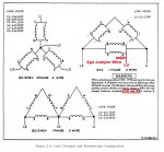
Here is the Connection Diagram for the 002A/003A to switch between single phase 120, single phase 120/240 and three phase 120/208

As you can see, Sewerzuk got closer to the actual single phase 120 configuration rather then the single phase 120/240

You would have to completely rewire your reconnection board to implement the single phase 120/240 configuration, meaning removing the movable board completely and then making up 2ga or 4ga wire jumpers - that's why a transformer solution is much simpler and safer

mep003a.jpg
 
Top