• Steel Soldiers now has a few new forums, read more about it at: New Munitions Forums!

  • Microsoft MSN, Live, Hotmail, Outlook email users may not be receiving emails. We are working to resolve this issue. Please add support@steelsoldiers.com to your trusted contacts.

MEP-004A, No output

flydude92

Member
118
13
18
Location
Waterville, Ohio
I can do this test but not until Monday. I won't be home tomorrow.
I did Sewerzuk's mod but I seem to remember his mod put 120V on H1/H2.
It's been a really long time but someone with a better memory might remember.
I can research it but not til Monday.
Brian
Brian,
No problem. If you did the mod exactly per Sewerzuks Video then you got 208 on T2 H1 / H2
If you didn't move the X8HH wire which connects to T2 H2 via J9 M from T8 to T11 then you wont get 120/208 output voltage, probably only half of that, but it wont burn out T2 - I verified this here when I bench tested the A11
I did download both of the videos you shot of your generator; your cycling problem is crazy!
I've never seen anything like that.
The fact that voltage cannot be adjusted tells me that the exciter/regulator circuit is the source of the problem, but I don't believe that I can point you toward a specific area to start troubleshooting.
I do, however, have a suggestion.
One member here on SS pointed out that I missed one lead movement; I haven't had another -004/-005 conversion to do so I haven't had the chance to re-test, edit, etc. my conversion process. However, I didn't feel any urgency in doing it, since the conversion has worked so well for so many people.
I don't know how thoroughly anybody has tested their sets after doing the conversion...perhaps your method of loading the set uncovered a problem with my conversion process on the -005's? I don't know...
The issue is this:
My lead movements changed the voltage being supplied to a control transformer inside of A11 from 240v to 120v. That control transformer supplies field current. It seems to work fine on the -004a, but maybe with the higher field current in the -005a it can't "keep up?" To correct this, you would need to move the X8HH16B lead from T8 to T7 (instead of from T8 to T11, as my conversion process currently shows).
I can't guarantee this will work, or fix your problem....but I have a feeling that it might.
From this thread I started: https://www.steelsoldiers.com/showt...Bank-Test-w-problems&highlight=t2+transformer

Post #11 and #12
I knew there was 120V going to T2. :naner:

Brian
 

peapvp

Well-known member
Steel Soldiers Supporter
1,138
1,291
113
Location
Basehor, KS
Brian,

thanks, like I said in post #300 that Sewerzuk's mod is in between 120 single and 120/208 single but it's really neither one.

The problem comes from the fact that Sewezuk had moved T2 H2, J9 M, X8HH from T8 to T11 which is neutral - he had left T2 H1, J9 L, (forgot wire number) on L3

He had disconnect the end of the L3 coil system from neutral and that changed the setup from WYE configuration to something you cannot find in any text book and connected the end of L3 coil to L2 which is now not used (floating)

With no load, this system will have somewhere from 120 to 208 VAC to Neutral on L3 - hence T2 will work for a while until the load on L3 changes and has to flow now through L2

Connecting T2 H2, J9 M, X8HH to T7 will connect it to L1 - now T2 is between L3 / L1 which should have stable 208VAC voltage. You can see this kind of cycling when your trying to synchronize two parallel Genset's incorrectly

A 240VAC single phase is 180 degrees out of phase - in Sewezuk's mod it could be anywhere from 120 degrees to 240 degrees, depending on how and how much load is connected

This whole thing may work, but this system is anything but stable.

Furthermore, one issue no one has ever mentioned in any of those mod posts is the Governor Load Measurement Unit A8

Even though not used in the utility version, but it is still installed in all 004A/005A's and connected as shown below........

You can imagine of what may happen if you apply 208VAC instead of the 120VAC on the primary of A8 T1...

The best thing is to disconnect all wires from A8 T1 on the reconnection board


GLMU.jpg

The Voltage on F1/F2 is neither DC or AC - it is switched from your VR - If you indeed have 3 VDC on it and VR puts out 48VDC then you would get

U/R = I

3V / 2.2 Ohm = 1.36 Amps

48V / 12.2 Ohm = 3.93 Amps ( 12.2 Ohm = Coil 2.2 Ohm + R1 10 Ohm )

3.93 Amps would blow your 3 Amp Fuse, never mind a 1 Amp Fuse - it's switched DC

So, the only way to check F1/F2 is with an oscilloscope, but you can use the 3 VDC as a good reference for trouble shooting.

It would be interesting to see what a VAC measurement would yield on F1/F2

both of those measurements combined will make a great reference when trouble shooting a excitation system


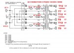
From this thread I started: https://www.steelsoldiers.com/showt...Bank-Test-w-problems&highlight=t2+transformer

Post #11 and #12
I knew there was 120V going to T2. :naner:

Brian
 
Last edited:

peapvp

Well-known member
Steel Soldiers Supporter
1,138
1,291
113
Location
Basehor, KS
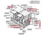
For anyone who doesn't know on where the Governor LMU A8 is located or what it looks like I attached the pic of it from Kris's 004A Utility Version here:

IMG_20190901_155253.jpg004A view1.jpg004A view2.jpg
 

peapvp

Well-known member
Steel Soldiers Supporter
1,138
1,291
113
Location
Basehor, KS
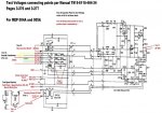
I also updated the A11 Schematic and added the Voltage Adjust Rheostat R2 on the front panel and how it is connected to the Voltage reconnection board

Simplified Schematic with Test Points for A11 Static Exciter Unit 2.jpg
 

flydude92

Member
118
13
18
Location
Waterville, Ohio
So, the only way to check F1/F2 is with an oscilloscope, but you can use the 3 VDC as a good reference for trouble shooting.
It would be interesting to see what a VAC measurement would yield on F1/F2
both of those measurements combined will make a great reference when trouble shooting a excitation system
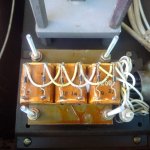
F1/F2 - 3.0 VDC and 4.26 VAC (I forgot to include it)

Brian
 

Guyfang

Moderator
Staff member
Moderator
17,029
24,888
113
Location
Burgkunstadt, Germany
Brian,

thanks, like I said in post #300 that Sewerzuk's mod is in between 120 single and 120/208 single but it's really neither one.

The problem comes from the fact that Sewezuk had moved T2 H2, J9 M, X8HH from T8 to T11 which is neutral - he had left T2 H1, J9 L, (forgot wire number) on L3

He had disconnect the end of the L3 coil system from neutral and that changed the setup from WYE configuration to something you cannot find in any text book and connected the end of L3 coil to L2 which is now not used (floating)

With no load, this system will have somewhere from 120 to 208 VAC to Neutral on L3 - hence T2 will work for a while until the load on L3 changes and has to flow now through L2

Connecting T2 H2, J9 M, X8HH to T7 will connect it to L1 - now T2 is between L3 / L1 which should have stable 208VAC voltage. You can see this kind of cycling when your trying to synchronize two parallel Genset's incorrectly

A 240VAC single phase is 180 degrees out of phase - in Sewezuk's mod it could be anywhere from 120 degrees to 240 degrees, depending on how and how much load is connected

This whole thing may work, but this system is anything but stable.

Furthermore, one issue no one has ever mentioned in any of those mod posts is the Governor Load Measurement Unit A8

Even though not used in the utility version, but it is still installed in all 004A/005A's and connected as shown below........

You can imagine of what may happen if you apply 208VAC instead of the 120VAC on the primary of A8 T1...

The best thing is to disconnect all wires from A8 T1 on the reconnection board


View attachment 776550

The Voltage on F1/F2 is neither DC or AC - it is switched from your VR - If you indeed have 3 VDC on it and VR puts out 48VDC then you would get

U/R = I

3V / 2.2 Ohm = 1.36 Amps

48V / 12.2 Ohm = 3.93 Amps ( 12.2 Ohm = Coil 2.2 Ohm + R1 10 Ohm )

3.93 Amps would blow your 3 Amp Fuse, never mind a 1 Amp Fuse - it's switched DC

So, the only way to check F1/F2 is with an oscilloscope, but you can use the 3 VDC as a good reference for trouble shooting.

It would be interesting to see what a VAC measurement would yield on F1/F2

both of those measurements combined will make a great reference when trouble shooting a excitation system
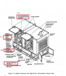
I never thought about A8, as you mentioned, it's not used in the utility set. I seem to remember running a set without an A8 installed, but I may be dreaming. I do know, that on the 400 set up, i never, ever, saw an A8 failure. Never. One of the few things I would bet large sums of money on. It simply was a non problem on the 004, 005 and 006 gen set.

F1 and F2 are switched? Never ever thought to mesure AC, as they get A VDC from the S9 during the start funtion. And I mesured VDC on the TB, when troubleshooting no output problems. We did not have an O scope in the shop set 4, so we never would have had the chance to look. Intresting. You two are miles ahead of me here. I was just a simple generator repair guy.
 

peapvp

Well-known member
Steel Soldiers Supporter
1,138
1,291
113
Location
Basehor, KS
Guy,

T7, T8, T9 will be the center tap connection when the reconnection board is moved to 400 - so they will be getting only 120 in this case

In the 200 system T7 is connected to T1 = L1, T8 is connected to T2 = L2 and T9 is connected to T3 = L3

the magic of the reconnection board, until you start modifying it....


I never thought about A8, as you mentioned, it's not used in the utility set. I seem to remember running a set without an A8 installed, but I may be dreaming. I do know, that on the 400 set up, i never, ever, saw an A8 failure. Never. One of the few things I would bet large sums of money on. It simply was a non problem on the 004, 005 and 006 gen set.

F1 and F2 are switched? Never ever thought to mesure AC, as they get A VDC from the S9 during the start funtion. And I mesured VDC on the TB, when troubleshooting no output problems. We did not have an O scope in the shop set 4, so we never would have had the chance to look. Intresting. You two are miles ahead of me here. I was just a simple generator repair guy.
 

peapvp

Well-known member
Steel Soldiers Supporter
1,138
1,291
113
Location
Basehor, KS
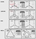
For simplification purposes, here are the standard Generator Coil Configurations for 3 Phase Systems

in this system you will get:

T7 / L0 = 120 VAC
T8 / L0 = 120 VAC
T9 / L0 = 120 VAC

T7 / T8 = 208VAC
T8 / T9 = 208VAC
T7 / T9 = 208VAC


3 phase connection diagram.jpg
 
Last edited:

peapvp

Well-known member
Steel Soldiers Supporter
1,138
1,291
113
Location
Basehor, KS
If you remove the Governor LMU A8 then you will loose the Reverse Power Protection Relay K15 - this affects only parallel operations of the Genset. This Relay K15 is not active unless you set your genset to parallel.

This is the reason why the Governor LMU A8 is installed in the Utility Versions as well since both, Tactical precise and utility can be used for parallel operations

AGAIN, IF YOU REMOVE A8 THEN YOU CAN NO LONGER USE YOUR GENSET FOR PARALLEL OPERATIONS!
 

peapvp

Well-known member
Steel Soldiers Supporter
1,138
1,291
113
Location
Basehor, KS
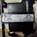
Follow the numbers - make sure you don't get H and X Side mixed up - the spacing between terminals is different - look very carefully at drawing and transformer - don't forget Wire Bridge between X2 and X3

If in doubt - use Ohm Meter and check for Resistance on either side between #2 and #6

If you measure Resistance between #2 and #6 that is your H Side - Infinite Ohm between #2 and #6 indicates X Side

Got the diagram. Also just got the trans an hour ago.
But looking at the trans I see no H's or X's.
Just 1 thru 8 on each side.
Kris
 
Top
AdBlock Detected

We get it, advertisements are annoying!

Sure, ad-blocking software does a great job at blocking ads, but it also blocks useful features of our website like our supporting vendors. Their ads help keep Steel Soldiers going. Please consider disabling your ad blockers for the site. Thanks!

I've Disabled AdBlock
No Thanks