• Steel Soldiers now has a few new forums, read more about it at: New Munitions Forums!

  • Microsoft MSN, Live, Hotmail, Outlook email users may not be receiving emails. We are working to resolve this issue. Please add support@steelsoldiers.com to your trusted contacts.

Help with mystery wire identification

Zeus51

Active member
154
47
28
Location
Birmingham, AL
Good evening,


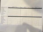
I am attaching a picture of a checklist of the lights so we are both understanding the same indications. based on the switch settings just put an "X" in the correct column and save as the same filename with CHG1 at the end of the file name. That way we can change the CHG number to keep up with things as we go.

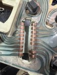
Also, before we go further let's take a look at the rear lights. If you disconnect the harness for all of the rear lights at the left rear of the frame we can test each circuit with a voltmeter to ground. there are only 4 wires to deal with 2 stop/tail/turn and 2 for backup. I want to know what is crossed for the right side to light up when the left turn signal is on.

Then we can figure out why backlight bulbs are flashing when the left turn signal is on.

Lastly, we can figure out the left marker light.

EDIT: I forgot a switch setting. Should be good to go now.
Alrighty, I finally had time to run it through the checks and make the sheet. See attached sheet
 

Attachments

deank

Well-known member
Steel Soldiers Supporter
313
490
63
Location
Florida
Ok. This is getting fun. First, let’s figure out why the right rear turn is on with the left turn.

Please first unplug the instrument cluster and double check that the printed circuit sheet is aligned with the connector socket correctly. Then plug it back in and retest the lights against the checklist on a fresh copy.

Then, with power off we need to check continuity of each wire of the right rear lamp sockets to the correct pin on the bulkhead connector. Then test the same wire to all other pins of the bulkhead connector. Test each lamp socket wire to ground also.

I know we will figure this out.
 

Zeus51

Active member
154
47
28
Location
Birmingham, AL
Ok. This is getting fun. First, let’s figure out why the right rear turn is on with the left turn.

Please first unplug the instrument cluster and double check that the printed circuit sheet is aligned with the connector socket correctly. Then plug it back in and retest the lights against the checklist on a fresh copy.

Then, with power off we need to check continuity of each wire of the right rear lamp sockets to the correct pin on the bulkhead connector. Then test the same wire to all other pins of the bulkhead connector. Test each lamp socket wire to ground also.

I know we will figure this out.
Ok. I unplugged the instrument cluster and tried to lightly brush one of the tabs. So now the tab fell off. I had the front left side marker wired the way the diagrams say. But I got to thinking, so I took that down and let’s one wire connected to brown and the grounded the second wire. And it started blinking with the blinker but it doesn’t light up constant with lights. It has the same result if I connect one wire to Lt Blue and then ground as well
 

Attachments

deank

Well-known member
Steel Soldiers Supporter
313
490
63
Location
Florida
Well, the printed circuit part sucks… I do not know what to tell you about that.

The left front side marker update is weird. I will dig back into the wiring diagrams for that.

Any luck checking wires for the right rear?
 

Zeus51

Active member
154
47
28
Location
Birmingham, AL
Well, the printed circuit part sucks… I do not know what to tell you about that.

The left front side marker update is weird. I will dig back into the wiring diagrams for that.

Any luck checking wires for the right rear?
Oh yeah. They all checked out for continuity. And they didn’t have any overlap or crosswires.

dude, I’m not really complaining about the circuit. It’s just my luck though.

After messing with the side marker, and knowing the Lt blue and dark blue wires check out for continuity and no cross wires, I can’t help but believe this is an issue in the dash or fuse box somewhere
 

deank

Well-known member
Steel Soldiers Supporter
313
490
63
Location
Florida
Ok. For the sake of checking everything, please try the turn signals and marker lights with the cluster unplugged. They may not function at all, but who knows…
 

Zeus51

Active member
154
47
28
Location
Birmingham, AL
Ok. For the sake of checking everything, please try the turn signals and marker lights with the cluster unplugged. They may not function at all, but who knows…
So after disconnecting the front left side marker and reconnecting again BUT with the cluster unplugged: neither the left side marker or the right or left indicators come on with the lights. however the blinkers work except the front left side marker that only blinks when one lead is grounded.

This is the craziest thing I’ve ever seen. I’ve checked continuity from the bulkhead to the bulb sockets for brown, Lt blue, dk blue. They all check out. I have a m1008 also, I even check the wiring in it and the m1008 is wired exactly the same.

its starting to feel like there’s a missing ground somewhere. Maybe I’m wrong
 
Last edited:

Zeus51

Active member
154
47
28
Location
Birmingham, AL
What about the rear with the cluster out?
Update: today, I looked at my m1008 again and decided I’d put the front left side marker socket back in that took off yesterday bc I know for a fact that it was wired correctly to start with. I took my time with the rewire making sure all the connections had continuity from bulkhead to Lt blue wire and brown wire the whole way.

and what do you know, all the lights and blinkers work correctly with and without the instrument cluster plugged in. Of course I can’t test the gauge cluster lights since that’s the little copper tab that broke off the printed circuit. So I guess I’ll be in the market for a whole gauge cluster with printed circuit now.

I‘m totally betting it’s going to stop working with the first bump I hit in the road. Nonetheless, I really appreciate all help and time you’ve taken.
 

deank

Well-known member
Steel Soldiers Supporter
313
490
63
Location
Florida
Very happy to about your success!
Are you able to trace what the circuit with the broken tab goes to?
 

deank

Well-known member
Steel Soldiers Supporter
313
490
63
Location
Florida
Hey again. Looking at the picture you sent of the printed circuit, it looks like that circuit is either for the seatbelt indicator bulb or the oil pressure light. First one not a problem, second one is a problem.
 

Valor

Active member
204
227
43
Location
Apple Valley, Ca.
Ok. I unplugged the instrument cluster and tried to lightly brush one of the tabs. So now the tab fell off. I had the front left side marker wired the way the diagrams say. But I got to thinking, so I took that down and let’s one wire connected to brown and the grounded the second wire. And it started blinking with the blinker but it doesn’t light up constant with lights. It has the same result if I connect one wire to Lt Blue and then ground as well
You might be able to get another circuit film at LMC truck. See if this link works for you.


Zeus51

Active member
154
47
28
Location
Birmingham, AL
Hey again. Looking at the picture you sent of the printed circuit, it looks like that circuit is either for the seatbelt indicator bulb or the oil pressure light. First one not a problem, second one is a problem.
I agree. I have been looking at the wiring diagrams and the missing tab on the circuit is the third tab up from the bottom. so the wire colors are the LT blue, dark blue then the Pink/Black wire that goes to the missing tab on the circuit. I noticed the same thing as you. The diagrams suggest it supplies power to a splice that goes to a bunch of things: seatbelt buzzer, cold advance temp sw, water in fuel solenoid, one fuse locations and powers the dash cluster backlighting.
 

RattleSnack

New member
9
20
3
Location
Ford City, PA
are they truly the same circuit as a cucv? With Gen and 4x4 lighting?
I remember reading up on this before. Check out this thread:

https://www.steelsoldiers.com/threads/which-lmc-printed-circuit-for-gauges.199401/

It appears that the printed curcuit for the idiot-light style is the same for the CUCV's. Here's a link to the one you want:

https://classicparts.com/1983-87-instrument-cluster-circuit-chevy

I believe the LMC version would be PN 38-8036

https://www.lmctruck.com/interior/dash-components/cc-1981-87-printed-circuits-and-retaining-clip
 

deank

Well-known member
Steel Soldiers Supporter
313
490
63
Location
Florida
Seems I was wrong. I followed the links above and saw a better picture of the printed citcuit. That third pin goes to the Gen 2 light.
My bad.
 

Zeus51

Active member
154
47
28
Location
Birmingham, AL
Seems I was wrong. I followed the links above and saw a better picture of the printed citcuit. That third pin goes to the Gen 2 light.
My bad.
Oh. I didn’t notice that. I did look at the printed circuits that RadioSnack advised and I think he’s right. They’re the same.
 
Top
AdBlock Detected

We get it, advertisements are annoying!

Sure, ad-blocking software does a great job at blocking ads, but it also blocks useful features of our website like our supporting vendors. Their ads help keep Steel Soldiers going. Please consider disabling your ad blockers for the site. Thanks!

I've Disabled AdBlock
No Thanks