• Steel Soldiers now has a few new forums, read more about it at: New Munitions Forums!

  • Microsoft MSN, Live, Hotmail, Outlook email users may not be receiving emails. We are working to resolve this issue. Please add support@steelsoldiers.com to your trusted contacts.

303M HydraMatic rebuild

rustystud

Well-known member
9,224
2,851
113
Location
Woodinville, Washington
035.JPG 
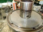
Using the special clamp tool again I compress the seal rings and install the rear drum assembly.
037.JPG038.JPG039.JPG

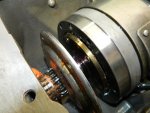
Now after installing the front and rear bands the drum assemblies are ready to go into the case. You need to "stab" the front shaft first angling the assembly into the case. The TM shows this. I don't have a helper to take pictures so I cannot show you how I do this .
041.JPG042.JPG
Once the assembly is in place and the main support is bolted down, you can pressure test the whole assembly.
043.JPG 
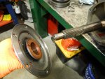
This hole applies the front clutch.
044.JPG This hole applies the rear clutch.

After tearing down everything due to the high leakage, I checked the iron seals for clearance. Since I only have four seal rings at this time, I never checked this as it is a moot point. You need a .002" and .007" feeler gauge to check this gap. The gap must be over .002" and under .007" .
Everything checked out as I figured it would. Since most likely the military rebuilt it last.
046.JPG051.JPG

Now everything is almost back to where I started this morning !
052.JPG053.JPG
 

rustystud

Well-known member
9,224
2,851
113
Location
Woodinville, Washington
I got the pistons back from the machine shop and reinstalled everything. Pressure tested it and all is fine.
But in the meantime, I tore down one of the five 303M transmissions I got in Canada two weeks ago and after cleaning it up found out it needs a new return wave spring in the reduction unit. This is becoming a problem. In the last four 303M transmissions I tore down; all needed a new return wave spring.
I am being forced to find a supplier of these wave springs if I want to complete this rebuild. There are several manufactures of wave springs, I just need to find one that makes one as big as the 303M needs.
Either that or a manufacture that is willing to make up some springs.
Since it has been fifty to sixty years since these transmissions have been built, these springs are shot. Putting one of these old springs back in service is just asking for trouble. Just like the one I tore down two months ago which had the wave spring shatter causing the apply piston to break.
So I'll continue rebuilding this transmission until I get to the reduction unit.
I need to cleanup a few more parts from the last 303M I tore down, then I'll get back to work.
 

rustystud

Well-known member
9,224
2,851
113
Location
Woodinville, Washington
I'm still tearing down one of the transmissions I picked up in Canada. Today I found out the cause of death for this transmission. Water. Seems the last owner took his M135 for a swim.
There was extensive damage to many different parts of the transmission. The reduction units clutches where severely worn. The front and rear clutch packs were destroyed. Literally ! The front pumps vanes were totally worn out. The rear pump had damage. The reverse piston had so much heat the lip seal melted, and the cast iron piston cracked in three places. So many areas had damage.
So today I was inspecting the front clutches more closely and found the friction plates were shedding their paper material. The only thing that can cause this is water.
I'm sure your asking how could water cause high heat in the reverse piston and extreme wear in the front and rear pumps. Well water is a terrible lubricant for metal parts and will destroy a pump used to pressurize oil. Since it had no oil to pump to the system just water, all those parts needing lubrication had nothing and overheated.
Now whoever did this tried to drain the water and add back transmission fluid, but it was too late. Probably drove it back home after taking a swim. When I was still in the "Marine's Motor Pool" we were taught that you immediately drained all fluids after taking a swim with a Deuce or any equipment really. The only time you were allowed to drive any distance was in a "combat" situation. Then you just drove it until it died.
So for your crazy guys who love to take your vehicles out and play hard with them, take notice here. Automatic transmission vehicles will get destroyed from water.
026.JPG024.JPG028.JPG Here you can see the melted seal.
027.JPGThere is melted rubber on the housing. It's the black spot at the top.
029.JPG031.JPGHere you can see the three cracks in the piston. I cleaned up the piston and then found the cracks. The piston was black from baked on oil.
036.JPGYou can see the wear on the pump vanes from the alignment rings.
003.JPGI've never seen this before. A bronze selective thrustwasher broken like this.
There must have been some nasty hammering of the input shaft to cause this. That combined with the lack of oil totally destroyed this washer.

This poor transmission died a terrible death !
 
Last edited:

rustystud

Well-known member
9,224
2,851
113
Location
Woodinville, Washington
OK, back to the rebuild.
Here's some pictures of my reassembly of the front and rear drum assemblies.
005.JPG006.JPGHere I'm installing the thrustwashers on the rear drum hub. This washer is the same size as the "Selective" thrustwasher used on the "Input Shaft" but it will not have a marking on it. The Selective thrustwashers have numbers stamped on them. Don't mix them up.
007.JPG008.JPG The hub is fully seated when it is parallel with the drum shown here.
013.JPG014.JPGThis is one of three "must" have tools to assemble the HydraMatic transmission. The center support ring compressor tool.
017.JPGInstall one of the three snap rings here after the center support is first installed. 016.JPG You compress the top sealing rings to install the rear drum assembly. You put the drum on the shaft and gently apply pressure pushing the ring compressor down.
My post several days ago shows this.

There is one important note I need to make here. The thrustwasher and metal ring installed on the front drum assembly is the same inner size as the front oil pump drive gear thrustwasher. The diference is the "outer" size. The oil pump drive gear uses a smaller thrustwasher while the front drum assembly uses a wider thrustwasher. Don't mix them up ! I will take pictures of this difference tomorrow.
 

Attachments

rustystud

Well-known member
9,224
2,851
113
Location
Woodinville, Washington
Here I'm installing the front pump.

013.JPG014.JPG016.JPG017.JPG
018.JPG This last picture is important. It's showing the raised edge of the pump you must have. The book calls for a protrudence of 0.003" to 0.015" . The reason for this is so the pump is held in place by the two bolts. If the pump did not protrude than the pump could spin in it's bore. Basically your
squishing the pump into the bore. The little washer is important to also help prevent the pump from spinning, but the clamping action is what really holds the pump in place.

A little side note; you can see I'm using stainless steel "Allen Head" bolts to hold the pump together instead of the #2 screws. This way I can actually torque the pump bolts and if needs be easily remove those pesky bolts later on.
 

rustystud

Well-known member
9,224
2,851
113
Location
Woodinville, Washington
Here's what I spent most of the day on. Cleaning parts like this oil pan. What I found after spending over three hours cleaning it due to the mess it was in, and all the heavy coats of paint on it was this nasty little crack.
021.JPG025.JPG023.JPG019.JPG
I was pretty pissed off when I saw this. I drilled a hole to prevent the crack from spreading in case some time down the road I needed this housing and have to weld it up.
What is really annoying is that crack should never have happened. He probably had a leak and instead of removing the fitting and putting on some thread tape or "Teflon" paste just decided to torque it down until it stopped leaking. That kind of "shade tree mechanicing" really makes me angry. Because of his stupidity he destroyed an irreplicable piece of equipment.
Just a note here; If a fitting leaks than remove it and put on some thread tape or paste and if that doesn't work, install another fitting. NEVER over tighten the fitting to stop the leak !
 

rustystud

Well-known member
9,224
2,851
113
Location
Woodinville, Washington
Spent a lot of time cleaning up another oil pan today. One item I need to mention is the oil pan "welch" plug, commonly called a "freeze plug" . This plug is on the side of the oil pan and is not mentioned in any repair manuals as normally you would never need to replace it. In a normal running vehicle with a transmission full of oil there would be no rust here. But if for some reason you need to use another oil pan on your transmission, you need to check for rust in this pans oil pick-up tube. Especially if the owner of said oil pan kept it outside. If you have rust present here you should go ahead and replace this Welch plug.
I drill a 1/2" hole in the center of the plug and using a tapered pry bar "pop" the plug out.
006.JPG004.JPG001.JPG
Thankfully this plug is a standard 1" freeze plug.
 

rustystud

Well-known member
9,224
2,851
113
Location
Woodinville, Washington
The other day I found something very interesting. I was cleaning up the "Output Shaft" when I noticed it was missing the "Input Shaft" to "Output Shaft" bushing. This is a small bushing (3/4" by 3/4" ) that acts like a "Pilot Bearing" on manual transmissions. It supports the end of the Input Shaft. It also acts as a restriction in the main lubrication oil passage. Without it, lubrication oil would just spray all over the place.
Think of it as a Main engine bearing (forget about the rod at this point) . Without it the engine would lose oil pressure and the components that needed this oil would be starved of oil. Yes the engine would operate for a while as the other bearings would help support the shaft, but it would fail much sooner than normal.
I installed a new bushing there, and it fit perfectly as it was completely machined out to except the bushing . So why was the bushing missing ? I checked the other shafts I had and all of them were missing this bushing. When I was an apprentice I don't remember this bushing being left out of a rebuild. That was over 40 years ago so maybe my memory is missing something. All my other HydraMatic rebuild manuals show this bushing and how to replace it. So why does the Military manual (TM 9-8025-2) "Not" show it ?
I do know the military manual is not complete, especially on the valve body. So was this bushing also missing from the manual ?
Would this help explain the short life span of the 303M HydraMatic Transmission ?
That is one thing that has been baffling me for some time now. A normal civilian HydraMatic will last well over 100,000 miles, but according to many individuals they claim the 303M transmission will only last 30,000 miles.
Now I have 4 more 303M transmissions outside waiting for tear down. If they also are missing this bushing that could be the "smoking gun" I've been looking for. Maybe they came this way from the factory by accident. Trust me it happens ! Since the military repair manual doesn't mention this bushing, the troops rebuilding this unit would also miss it. This could be the whole reason this transmission got such a bad rap. One missing bushing.
Of course I could be totally wrong.

img015.jpgimg016.jpg
 

USMC 00-08

Well-known member
1,176
165
63
Location
Skiatook, OK
I tore down one of the five 303M transmissions I got in Canada two weeks ago and after cleaning it up found out it needs a new return wave spring in the reduction unit. This is becoming a problem. In the last four 303M transmissions I tore down; all needed a new return wave spring.
I am being forced to find a supplier of these wave springs if I want to complete this rebuild.
Since it has been fifty to sixty years since these transmissions have been built, these springs are shot. Putting one of these old springs back in service is just asking for trouble. Just like the one I tore down two months ago which had the wave spring shatter causing the apply piston to break.
Is this what I have read about on here referred to as the "wavy release spring"? Seems like some people were saying to just remove it and things would function fine. I'll see if I can find that thread and if I remember correctly it might have been in the write up called Hydramatic Heaven by Major Tom.

Found it! Look at the fourth paragraph.


That is one thing that has been baffling me for some time now. A normal civilian HydraMatic will last well over 100,000 miles, but according to many individuals they claim the 303M transmission will only last 30,000 miles.
Now I have 4 more 303M transmissions outside waiting for tear down. If they also are missing this bushing that could be the "smoking gun" I've been looking for. Maybe they came this way from the factory by accident. Trust me it happens ! Since the military repair manual doesn't mention this bushing, the troops rebuilding this unit would also miss it. This could be the whole reason this transmission got such a bad rap. One missing bushing.
Of course I could be totally wrong.

View attachment 933346View attachment 933347
That is very interesting. Hopefully you have found the problem!
 

rustystud

Well-known member
9,224
2,851
113
Location
Woodinville, Washington
Is this what I have read about on here referred to as the "wavy release spring"? Seems like some people were saying to just remove it and things would function fine. I'll see if I can find that thread and if I remember correctly it might have been in the write up called Hydramatic Heaven by Major Tom.

Found it! Look at the fourth paragraph.


That is very interesting. Hopefully you have found the problem!
Yes that is the "wavy spring" I'm referring too. You do need this spring contrary to what this gentleman said. Without it the piston will "drag" on the reaction carrier, causing wear and heat and ultimately wearing out the friction material on the piston.
 

rustystud

Well-known member
9,224
2,851
113
Location
Woodinville, Washington
Took some pictures of the "output shaft" bushing. This will show you how important this bushing is.
013.JPGHere's the busing in question. it fits into the output shaft.
015.JPGI'm showing how the bushing will fit the input shaft.
023.JPGHere the bushing is installed and the "selective" thrustwasher is in place.
018.JPGThis is how the two shafts look together.
025.JPGWithout this bushing, the only thing supporting the input shaft is the planetary gears in the output shaft. This would allow the input shaft to "wobble" all over the place besides allowing the oil pressure to crash.
 
Top