• Steel Soldiers now has a few new forums, read more about it at: New Munitions Forums!

  • Microsoft MSN, Live, Hotmail, Outlook email users may not be receiving emails. We are working to resolve this issue. Please add support@steelsoldiers.com to your trusted contacts.

Air conditioner install using Waterloo parts

ramdough

Well-known member
1,554
1,729
113
Location
Austin, Texas
OK @ramdough I couldn't wait until the weekend.

Here's some pics, but the gist of it is the front most hose is the inflow. If it trace that line back, it goes down along the passenger frame rail, then up towards the front of the engine near the front crank pulley. Both hoses lead here, one stops short (lower on the engine), and that's the return. The feed line feeding flow into the heater box comes from higher up.

I hope that makes sense.

View attachment 880157
View attachment 880158
View attachment 880159
Thanks! That will help a lot!


Sent from my iPhone using Tapatalk
 

Guruman

Not so new member
Steel Soldiers Supporter
Got my interior unit installed today. It was a lot of work, but not a lot of drama. I found it helpful to sit the unit on top of a couple of 2x4's, as well as removing the lower portion of the gunner's platform. That gave me more room to move the unit around to get the wiring and air lines sorted out, and kept the drain tubes from getting scraped off.

A luck test revealed that the unit seems to be working fine, however my new options panel is inop, no tach, no switch illumination. I thought I remember reading something about connector under the PDP that needs hooked up to the available connector from the options panel, but I cannot find the thread, and wherever that connector is hiding, is doing it good.
 

Guruman

Not so new member
Steel Soldiers Supporter
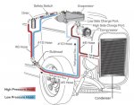
Got my condenser unit bolted up... starting to look into the hose routing. I'm a little unsure on how the whole system gets plumbed in.

So far I think the output of the pump gets a hose leading to the high pressure service port, then into the dryer, then into the condenser (top or bottom connection???), then into the evaporator, then back to the pump.

But... some diagrams I see online show the flow running into the condenser first, then into the dryer... does it matter?

Also, I think I need a crimper to fab up the lines. I ordered one from Amazon this morning, hopefully it does the job.

https://www.amazon.com/gp/product/B07S528V2N/
 

ramdough

Well-known member
1,554
1,729
113
Location
Austin, Texas
Got my condenser unit bolted up... starting to look into the hose routing. I'm a little unsure on how the whole system gets plumbed in.

So far I think the output of the pump gets a hose leading to the high pressure service port, then into the dryer, then into the condenser (top or bottom connection???), then into the evaporator, then back to the pump.

But... some diagrams I see online show the flow running into the condenser first, then into the dryer... does it matter?

Also, I think I need a crimper to fab up the lines. I ordered one from Amazon this morning, hopefully it does the job.

https://www.amazon.com/gp/product/B07S528V2N/
The routing does matter. The path through the condenser matters too. The condenser is after the compressor (in the top and out the bottom), then the dryer, then the evaporator, then compressor again.

Broke Overland has a good video.

I am a little unsure about where the trinary switch goes, but I think it is ported into the dryer some how.


Sent from my iPhone using Tapatalk
 

Guruman

Not so new member
Steel Soldiers Supporter
The routing does matter. The path through the condenser matters too. The condenser is after the compressor (in the top and out the bottom), then the dryer, then the evaporator, then compressor again.

Broke Overland has a good video.

I am a little unsure about where the trinary switch goes, but I think it is ported into the dryer some how.


Sent from my iPhone using Tapatalk
Ya... his video is partly why I have questions.... he mentions that the flow through his condenser seems wrong... should be gas in the top. liquid out the bottom, but he shows the high pressure going in the bottom.
 

GeneralDisorder

Well-known member
Steel Soldiers Supporter
2,000
5,127
113
Location
Portland, OR
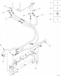
Here's the FMTV A1 LSAC AC system drawings:

FMTV AC Hoses.jpg

Item #3 is the suction hose (low side) from the evaporator to the compressor. This connects to a 90 degree pipe with a support bracket that fits into the back of the compressor. The low side charge fitting is part of the fitting on the back of the compressor. This hose is the largest diameter and the factory hose is also insulated.

Item #1 is the discharge hose (high side) from the compressor to the condenser. This hose contains the high side charge fitting as an inline splice in the hose nearer to the compressor.

Item #5 is condenser to drier.

Item #8 is drier to evaporator.

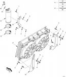
FMTC AC Condenser Drier.jpg

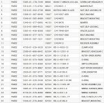
Trinary switch is going to go into the drier - where the factory setup has one of the two pressure switches - 16 in that diagram.
 

ramdough

Well-known member
1,554
1,729
113
Location
Austin, Texas
Ok,

Few issues here….


I have everything but I am missing a few bolts.

Can someone confirm the following guesses? I hope to order today from McMaster.

Compressor to bracket: 4ea m10x1.5 x 100mm?


Upper bracket to lower bracket: 4ea m10x1.5 x 30mm?

Condenser: guessing m10x1.5 x 30mm?

Cat pulley: m10x1.5 x 85mm (I have these but confirming).

Anyone know the belt size?


Sent from my iPhone using Tapatalk
 

chucky

Well-known member
Steel Soldiers Supporter
6,612
18,937
113
Location
TN .
Ok,

Few issues here….


I have everything but I am missing a few bolts.

Can someone confirm the following guesses? I hope to order today from McMaster.

Compressor to bracket: 4ea m10x1.5 x 100mm?


Upper bracket to lower bracket: 4ea m10x1.5 x 30mm?

Condenser: guessing m10x1.5 x 30mm?

Cat pulley: m10x1.5 x 85mm (I have these but confirming).

Anyone know the belt size?


Sent from my iPhone using Tapatalk
I think i would throw the towel in at this point ! It wasnt ever gona workout so cut your losses ! Box all the stuff up and i will have someone come by and haul the stuff off ! Those bolt prices are thru the roof now just save your money !
 

ramdough

Well-known member
1,554
1,729
113
Location
Austin, Texas
Here's the FMTV A1 LSAC AC system drawings:

View attachment 881104

Item #3 is the suction hose (low side) from the evaporator to the compressor. This connects to a 90 degree pipe with a support bracket that fits into the back of the compressor. The low side charge fitting is part of the fitting on the back of the compressor. This hose is the largest diameter and the factory hose is also insulated.

Item #1 is the discharge hose (high side) from the compressor to the condenser. This hose contains the high side charge fitting as an inline splice in the hose nearer to the compressor.

Item #5 is condenser to drier.

Item #8 is drier to evaporator.

View attachment 881105

Trinary switch is going to go into the drier - where the factory setup has one of the two pressure switches - 16 in that diagram.
Is #6 a rubber grommet?


Sent from my iPhone using Tapatalk
 

ramdough

Well-known member
1,554
1,729
113
Location
Austin, Texas
Here's the FMTV A1 LSAC AC system drawings:

View attachment 881104

Item #3 is the suction hose (low side) from the evaporator to the compressor. This connects to a 90 degree pipe with a support bracket that fits into the back of the compressor. The low side charge fitting is part of the fitting on the back of the compressor. This hose is the largest diameter and the factory hose is also insulated.

Item #1 is the discharge hose (high side) from the compressor to the condenser. This hose contains the high side charge fitting as an inline splice in the hose nearer to the compressor.

Item #5 is condenser to drier.

Item #8 is drier to evaporator.

View attachment 881105

Trinary switch is going to go into the drier - where the factory setup has one of the two pressure switches - 16 in that diagram.
Do you have the full drawing you could post with parts list?


Sent from my iPhone using Tapatalk
 

GeneralDisorder

Well-known member
Steel Soldiers Supporter
2,000
5,127
113
Location
Portland, OR
Belt is 1/2" wide, 55" long.

Compressor to bracket bolts are 10x1.5x110mm

Upper to lower bracket are 10x1.5x30mm

Condenser to frame - what you suggest should work. I grabbed what I needed from my bolt bins and didn't pay attention to size.

Crankshaft pulley bolts are 10x1.5x85mm
 

ramdough

Well-known member
1,554
1,729
113
Location
Austin, Texas
Belt is 1/2" wide, 55" long.

Compressor to bracket bolts are 10x1.5x110mm

Upper to lower bracket are 10x1.5x30mm

Condenser to frame - what you suggest should work. I grabbed what I needed from my bolt bins and didn't pay attention to size.

Crankshaft pulley bolts are 10x1.5x85mm
Thanks! I ordered my bolts!


Sent from my iPhone using Tapatalk
 

ramdough

Well-known member
1,554
1,729
113
Location
Austin, Texas
OK @ramdough I couldn't wait until the weekend.

Here's some pics, but the gist of it is the front most hose is the inflow. If it trace that line back, it goes down along the passenger frame rail, then up towards the front of the engine near the front crank pulley. Both hoses lead here, one stops short (lower on the engine), and that's the return. The feed line feeding flow into the heater box comes from higher up.

I hope that makes sense.

View attachment 880157
View attachment 880158
View attachment 880159
Ok, finally traced my hoses. The hoses are reversed. When I switch them back, we will know if that makes a difference with heat always on. Will update everyone.


Sent from my iPhone using Tapatalk
 

ramdough

Well-known member
1,554
1,729
113
Location
Austin, Texas
Should I paint my pulley? At least the non contact surfaces?


I was surprised that it was just bare steel.


Sent from my iPhone using Tapatalk
 
Top