Goldneagle,
There is a special type side cutter, made just to cut wire ties. It blunts the wire tie cut edge. You will never cut yourself again after using them. Nice.
Your plan sounds good, but keep in mind when you use the rubber baby bumpers between the flat stock and skids, that you reduce the grounding surface area. CECOM, (Communication and Electronics Command), would never let us do something like that. Grounding problem.
I always maintained that the bolts holding the set to the trailer would be sufficient for grounding purposes. As a lowly Warrant, I could never win this fight. I even suggested that we could run ANOTHER, (so we now had two, instead of just one ground path) ground wire from the generator to the trailer. The engineers would never buy off on it. The party line was that if the tie down bolts were loose, you had no real ground between the gen set, trailer and ground rod. When the set is at least in contact with the trailer it is "somewhat" grounded. I did not agree then, and still don't agree now. But I would run another ground wire from LO to a central ground point on the trailer.

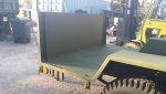 59.3 KB Views: 38
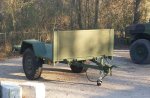 93 KB Views: 41