• Steel Soldiers now has a few new forums, read more about it at: New Munitions Forums!

  • Microsoft MSN, Live, Hotmail, Outlook email users may not be receiving emails. We are working to resolve this issue. Please add support@steelsoldiers.com to your trusted contacts.

Goldneagle's M116A1 Generator Trailer restore and modification thread

goldneagle

Well-known member
4,437
872
113
Location
Slidell, LA
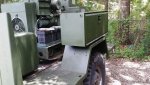
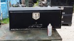
Well I had another productive day today. Tool box repaint and installation.

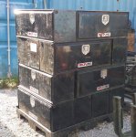
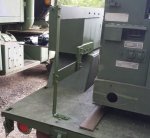
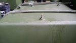
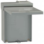
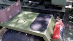
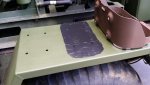
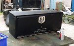
I stated by removing the plastic hole plugs from the tool box. Sanded the whole tool box with DA Sander. Cleaned it up with acetone. Applied polyurethane calk tot he plugs and reinstalled them. Used some vinyl to patch over 2 drill holes in the back of the box.

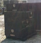
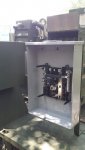
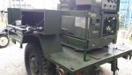
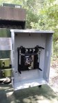
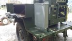
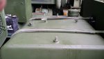
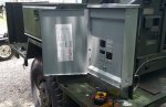
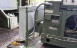
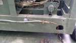
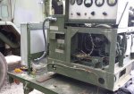
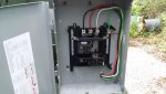
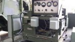
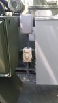
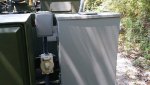
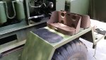
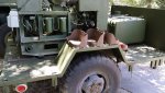
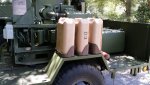
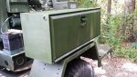
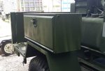
Drilled 3/8" holes in 4 rubber hockey pucks. Primed and painted tool box with Green CARC substitute paint from Rapco. Drilled 4 holes in the bottom of the tool box to bolt to top of fender on driver side of trailer. Installed the tool box on top of the rubber hockey pucks and secured with (4) 5/16" bolts. Applied touch up paint.

Here are the pictures:
 

Attachments

goldneagle

Well-known member
4,437
872
113
Location
Slidell, LA
I got the 3 phase electrical panel in last night from AMAZON.COM. The physical dimensions were a bit bigger than I envisioned. I had planned to mount the panel on the side of the tool box I mounted earlier this week. When I placed the box against the side of the tool box I could see some issues in mounting it there.

1) the distance of the box mounting holes were wider than the tool box.

2) if I mounted the panel in that location it will interfere with the trailer bow that is attached right behind the wheel fender.

So after a lot of measuring and remeasuring as well as multiple design ideas I finally settled on the location and mounting design for the panel.

I ended up using some 3/8" x 3" flat stock I had left over from the generator mounting. I attaching the flat stock to the back of the tool box and extending it 20" to the right of the tool box. I mounted the panel parallel to the back of the tool box. Here are the pictures:
 

Attachments

goldneagle

Well-known member
4,437
872
113
Location
Slidell, LA
I was trying to figure out how to solve the vent issues with the fuel tank I installed. Juan Prado suggested using axle vents. Found a good deal on axle vents with 1/8" pipe thread on AMAZON.COM. Only $2.06 each! They fit perfectly on the 2 small ports of the fuel tank.
 

Attachments

goldneagle

Well-known member
4,437
872
113
Location
Slidell, LA
Picked up electrical supplied yesterday.

Drilled 1-1/8" hole on the side of the splice box on the generator set. Installed 3/4" Liquidtite non-metalic flex conduit between the splice box and electric panel. Inserted (4) #6 THHN wires into the Liquidtite.

Connected the #6 wires to the acorn splices inside the box. I am using Green as Neutral/Ground. L1 - Black, L2 - White (3 phase only), L3 - Red, L0 - Green (Neutral)

Connected the 4 wires inside the 3 phase panel. White wire (L2 went on the 3rd lug) Secured the 3/4" Liquidtite with (2) 3/4" pipe straps.

Ran #8 stranded UF wire for ground. Connected to existing ground with acorn connector. Secured with wire strap to generator frame assembly. Attached to ground/neutral bus in the panel.

I cranked up the generator after turning the selector switch to 3 phase power. Tested the mail lugs in the circuit breaker panel and got 220 volt between the 3 HOT conductors (L1-L2, L1-L3, L2-L3) Got 120 volt to ground/neutral (L1-L0, L2-L0, L3-L0)

All is good! See pictures:
 

Attachments

goldneagle

Well-known member
4,437
872
113
Location
Slidell, LA
GE, your build threads are all saved on my favorites because the quality and time you put into each build is simply amazing!
Thank you. I am humbled by your praise.

Going to make up a custom outlet box from a gutted 3R exterior panel. Hopefully I can do it tomorrow.
 

Attachments

goldneagle

Well-known member
4,437
872
113
Location
Slidell, LA
Well that idea did not work out. Not enough depth in the box for the cover to close over the outlet and plug. I returned the panel to Home Depot and purchased (2) 50 amp 240 volt RV receptacle boxes.

I replaced one of the 50 AMP outlets with a older style 3 prong 50 AMP 240 Volt outlet. This is the type used with both my welders as well as the 50 AMP Power extension cords I use to tie in the house to the generator in a power out.

The 2nd receptacle box has the 4 prong 50 amp 125/250 Volt outlet. I will be feeding it with a 40/40 circuit breaker.

I mounted the 2 receptacle boxes on the front of the generator below the control panel. There is plenty of room to operate the throttle control. It does not look like it in the picture, but the angle is deceiving.

I hope to run and tie in the wires tomorrow.
 

Attachments

goldneagle

Well-known member
4,437
872
113
Location
Slidell, LA
Yesterday I sanded, primed, and painted 3 Jerrycan Holders.

Today I installed them on the right fender of the trailer. In the pictures you will see I applied a black substance to the fender location where each Jerrycan holder will sit. I used a pencil to outline the location of each base. I then applied a coat of polyurethane calk to each area and spread it with a speckling knife.

The reason behind this is because the fenders and bottom of the Jerrycan holders were pitted from water getting trapped between the 2 surfaces and rusting the metal. The calking will keep the water out and protect the metal surfaces.
 

Attachments

goldneagle

Well-known member
4,437
872
113
Location
Slidell, LA
I am waiting for a SteelSoldiers member to get back to me with info for shipping me 8 used 5 ton cargo bow corners. I will use the bow corners to assemble custom bows for my trailer.

I need to know the correct height of the bows from top of trailer bed. Can anyone provide the measurement.

I am also looking for a good deal on a M116A1 vinyl cover.
 

Guyfang

Moderator
Staff member
Moderator
16,083
22,684
113
Location
Burgkunstadt, Germany
Can you take a picture of the trailer data plates. Then I can tell you the height of the bows, when I know what manual to look at.
 

goldneagle

Well-known member
4,437
872
113
Location
Slidell, LA
Can you take a picture of the trailer data plates. Then I can tell you the height of the bows, when I know what manual to look at.
All the info I could get from any readable data tag is: US Power Unit T-62-028-16 PU-620/M KW 5 Hertz 60 1961 NSN: 6115-00-738-6340
 

Guyfang

Moderator
Staff member
Moderator
16,083
22,684
113
Location
Burgkunstadt, Germany
Goldneagle,

This was a very strange, and interesting thing. The TM's that covers your M116A1 trailer, TM 9-2330-202-14 and the TM that covers the PU, (Power unit) PU-620/M, TM 9-6115-365-15, (changes 1-7) do not show any bow or canvas for the PU set. And that's just not right! I remember working on this PU, for probably several hundred hours. There is a picture of a similar PU set, that shows the canvas being slightly higher then the metal end plate that goes up front. That plate is slightly higher then the 5 KW gasser gen sets, (X2) in the bed of the trailer.

The PU-620/M I worked on, and we had two of them, must have had canvas and bows from another PU set. They were high enough to allow us to work on the gen sets, with the sides and ends rolled up, and still be under the top canvas. You had to bend over a bit, but doable. So I guess what I am getting at, is that you can do what you want on this trailer. I will say, we had all steel bows. Normally on such trailers, we had a metal curved part on each side, and wood uprights and crosspieces. Bolted together. Perhaps because the set up we used had so much wind resistance, (burning down the Autobahn's) it was better to have steel bows, I don't know. Should you wish to look at the TM, I will be happy to post it.

The reason these trailers are around at all, is because of the desert wars. The army had to admit that having a bunch of skid mounted TQG's was dumb. So all kinds of trailers were pulled out of DRMO's, POMCUS, scrap yards and the like. Then "repaired" before being "Modified" for gen sets that were not intended to be mounted on them. We jumped through a lot of hoops get get this done. Not always right. Then TACOM started up a program to get real trailers made, but that's another story. Good luck with this trailer, it's lookin good!!
 

goldneagle

Well-known member
4,437
872
113
Location
Slidell, LA
Goldneagle,

This was a very strange, and interesting thing. The TM's that covers your M116A1 trailer, TM 9-2330-202-14 and the TM that covers the PU, (Power unit) PU-620/M, TM 9-6115-365-15, (changes 1-7) do not show any bow or canvas for the PU set. And that's just not right! I remember working on this PU, for probably several hundred hours. There is a picture of a similar PU set, that shows the canvas being slightly higher then the metal end plate that goes up front. That plate is slightly higher then the 5 KW gasser gen sets, (X2) in the bed of the trailer.

The PU-620/M I worked on, and we had two of them, must have had canvas and bows from another PU set. They were high enough to allow us to work on the gen sets, with the sides and ends rolled up, and still be under the top canvas. You had to bend over a bit, but doable. So I guess what I am getting at, is that you can do what you want on this trailer. I will say, we had all steel bows. Normally on such trailers, we had a metal curved part on each side, and wood uprights and crosspieces. Bolted together. Perhaps because the set up we used had so much wind resistance, (burning down the Autobahn's) it was better to have steel bows, I don't know. Should you wish to look at the TM, I will be happy to post it.

The reason these trailers are around at all, is because of the desert wars. The army had to admit that having a bunch of skid mounted TQG's was dumb. So all kinds of trailers were pulled out of DRMO's, POMCUS, scrap yards and the like. Then "repaired" before being "Modified" for gen sets that were not intended to be mounted on them. We jumped through a lot of hoops get get this done. Not always right. Then TACOM started up a program to get real trailers made, but that's another story. Good luck with this trailer, it's lookin good!!
I would like to get the proper vinyl top for a M116 generator trailer. Therefor I need the standard height of the top of bows so I can fabricate the proper height staves that will eventually support the vinyl top. It does not matter to me if it is specifically for the PU-620/M since I do not have those generators anyway.
 

Guyfang

Moderator
Staff member
Moderator
16,083
22,684
113
Location
Burgkunstadt, Germany
Do you want to be able to work under the tarp? Or do you want to roll the tarp up and take off bows when you have to work or repair something? There are several different types of tarps for the M116A1 trailer with the type of bed you have. The standard cargo body tarp and bows will not fit your trailer. The bows and tarp for a PU-751M would probably work for your trailer.

The bows have a NSN of: 2540-00-926-0994
The tarp has a NSN of: 2540-00-926-0993

Look in your browser for a web site called OSG PARTS. Type in the NSN, and look them up. Click on the NSN, and that will take you to a list of characteristics. It lists height, width and length and so on.

Should you wish to look at a diagram of what the PU-751M set up looks like, look in TM 5-6115-630-14 &P. If you want a copy, I can upload it if you need it.
 
Last edited:

SCSG-G4

PSVB 3003
Steel Soldiers Supporter
5,321
3,242
113
Location
Lexington, South Carolina
105 generator trailer bows are 62" high in the middle when installed. My 116 bows seem to have disappeared at the club compound, so they probably got sent to the scrapper by the OCD neat freaks.
 

goldneagle

Well-known member
4,437
872
113
Location
Slidell, LA
Do you want to be able to work under the tarp? Or do you want to roll the tarp up and take off bows when you have to work or repair something? There are several different types of tarps for the M116A1 trailer with the type of bed you have. The standard cargo body tarp and bows will not fit your trailer. The bows and tarp for a PU-751M would probably work for your trailer.

The bows have a NSN of: 2540-00-926-0994
The tarp has a NSN of: 2540-00-926-0993

Look in your browser for a web site called OSG PARTS. Type in the NSN, and look them up. Click on the NSN, and that will take you to a list of characteristics. It lists height, width and length and so on.

Should you wish to look at a diagram of what the PU-751M set up looks like, look in TM 5-6115-630-14 &P. If you want a copy, I can upload it if you need it.
OK I got the dimensions I need. I also requested a price and availability for the cargo cover. BOWS: L = 72.25" , H = 54.5" , Thickness = 0.073 to 0.093" max , Inside corner radius: 4.25" , Mounting End Thickness: 1"

TARP: L = 95" , H = 63" , W = 72.5"

So a 16' x 20' tarp would work in a pinch.
 
Top