• Steel Soldiers now has a few new forums, read more about it at: New Munitions Forums!

  • Microsoft MSN, Live, Hotmail, Outlook email users may not be receiving emails. We are working to resolve this issue. Please add support@steelsoldiers.com to your trusted contacts.


HanksDeuce: 8" Lift, Bobbed, External Cage, A/C and more Project!

HanksDeuce

Well-known member
1,080
238
63
Location
Prairieville, LA
Great weather today so I decided to continue my engine swap. Here is another shot of the passenger side bellhousing mount that was finished last week. Tons of room in the engine bay. Note the surface rust on the bellhousing mount from a few days in Louisiana humidity (even with the hood shut). I'll paint everything later after mock-up is complete.

IMG_2989.jpg

Today I installed the driver side bellhousing mount. Again, tons of clearance. Leave it up to an engineer (me) to provide the fabricator (Kyle) with a sketch to create the bellhousing mounts from. No shims are required. I always heard behind every bad welder there's a great grinder. Maybe behind every bad engineer there's a great fabricator. Black Rock Fab has never let me down yet. I sketch it and he fabs it. Once I finish the front engine mount I will drill through the top frame rail for the bellhousing mounts. Then I will install the frame rail stiffeners. The bellhousing mount pucks will crush some, so they look a little loose in the pics.

IMG_2986.jpg IMG_2987.jpg

Below is a shot of what I have to work with for the front engine mount.

I'm thinking of 2 options:
  1. Mandrel bent DOM tubing that snakes around the front of the oil pan, catches the front engine mount, and bolts to the bottom flange on the frame.
  2. Make a mounting block that catches the 2" .250 DOM cross tube behind the "Molon Labe" front lift block cross-plate. The tube is the cross bar for the 8" lift blocks.
IMG_2980.jpg
 

HanksDeuce

Well-known member
1,080
238
63
Location
Prairieville, LA
While waiting on BlackRockFab to finish my front engine mount I decided to tackle the weakest link on a 12v Cummins motor, the killer dowel pin.

Attached are pictures of pushing the dowel pin back in, removing one of the front cover bolts, and putting a capture tab on the bolt. Cheap insurance!
 

Attachments

HanksDeuce

Well-known member
1,080
238
63
Location
Prairieville, LA
Since the Cummins 6BT doesn't require an electric lift pump I decided to modify the existing M35A2 lift pump to fit my needs. I purchased a few bulk head 90 degree fittings and 40 feet of stainless tubing from a local stainless steel distributor. I'm using 1/2" 0.035 wall tubing for the supply and 3/8" 0.035 wall tubing for the return & vent lines.

The supply line gets extended down to the bottom of the fuel tank and includes a bevel cut for maximum flow. I borrowed a tubing bender from a friend down the street. That 1/2" tubing takes a bit of effort to bend!

I got tired of the same old wet spot forming on top of the fuel tank. Some time back I took the pump out and fixed the supply line that almost popped off. At that time I put on a new gasket and tightened the screws down. It still stayed wet around the ring. Fast forward to the present. I reused the gasket, but on both sides of the gasket I used my new friend, Permatex The Right Stuff. This product is amazing! No more wet fuel pump ring.
 

Attachments

HanksDeuce

Well-known member
1,080
238
63
Location
Prairieville, LA
I decided to take off the exhaust manifold and turbo assembly for a quick re-paint. This is a very weird exhaust manifold from Freightliner compared to the typical 12v Cummins found in a pick-up truck.

The paint used:
Dupli-Color Engine Enamel DE1638 (Cummins Beige)
VHT FlameProof (Flat Black)

I also took the time to drill & tap the 1/4" NPT required for the pyrometer (exhaust gas temperature) probe.
 

Attachments

HanksDeuce

Well-known member
1,080
238
63
Location
Prairieville, LA
I got bored one weekend and decided to pay CSM Davis a visit in Mississippi. What a great guy! He took me for a quick tour of Camp Shelby. Boy I was drooling at the MV inventory they have out there. Oshkosh PLS and green iron for days.

While I was there I picked up a spare tire rack and a few toolboxes for my deuce. I could have bought more, but my Ford Expedition ran out of room for stuff on the return trip!

Here are pictures of a spare 16R20 Michelin XZL on the rack. Almost everything was stripped off the rack except the davit base and wedge plate so I could move things around. Looks like I have to widen the rack to fit the 53" tire. I'll go buy some plate from a local steel shop, cut the ribs, and get a friend to weld the longer ribs in.

I'm glad I found a solution to storing a spare 53" wheel/tire combo on my deuce. I didn't want to use one of those cheap China Freight hoists in the bed.

Now... the difficult part... cutting 9 inches out of my M105A2 bed. Oh the agony.
 

Attachments

HanksDeuce

Well-known member
1,080
238
63
Location
Prairieville, LA
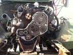
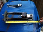
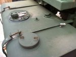
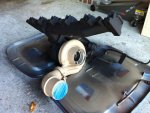
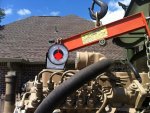
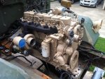
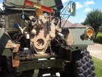
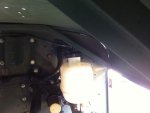
The first picture is an update from the re-painted exhaust manifold and turbo that were reinstalled. You will also see that the engine was touched up using the Cummins Beige paint as well. Turned out a lot better than I had expected!

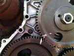
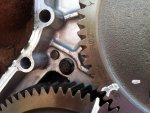
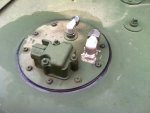
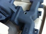
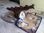
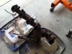
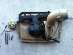
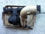
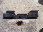
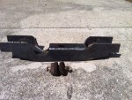
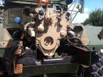
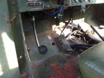
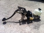
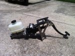
The rest of the pictures are for the front engine mount.

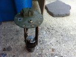
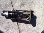
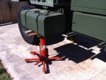
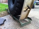
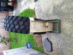
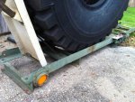
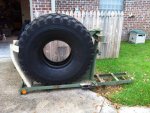
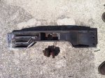
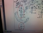
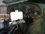
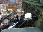
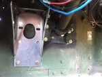
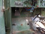
So Kyle at BlackRockFab sent over the front engine mount for my Cummins 6BT swap. The bellhousing mounts were already installed months ago, so this is the third and final mount for the engine/tranny. I can adjust the downward angle of the engine by placing large shims (washers) under the Cummins front mount, but above the rubber isolators that sit inside Kyle's mount. This is how Freightliner had it from the factory. See the attached parts manual page for reference. The coped area is for the lower radiator neck to fit through. I probably could have reused the factory deuce front cross member after a bunch of coping/welding/cussing, but I know that Kyle's cross member is a BEAST and will do the job better than anything else would! :D 
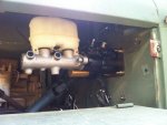
With 3 washers under the front engine mount the downward angle is 3.5-4 degrees. This matches what Freightliner had in the Thomas Built bus that I used as a donor vehicle. Other people have installed their engines completely flat, but they offset the engine to one side at a slight angle so that the driveshaft needle bearings don't wear out.
 

Attachments

Last edited:

HanksDeuce

Well-known member
1,080
238
63
Location
Prairieville, LA
I'm very excited about this post. This post makes me happy. Time to talk about a split system Hydroboost brake setup.

For those people that can quickly find something wrong with everything - YES the brake pedal is quite a bit off to the left side. I will "manipulate" the pedal into the factory deuce brake pedal spot soon. I contemplated 2-3 hours on where to put that big pedal assembly. The darn steering shaft got me every time. One time I thought I had it licked but when I measured in the engine bay the fuel filter was an interference. To the left side of the steering shaft I went. Tons of room with the hood closed. I can even re-use my Waterloo power steering reservoir in the same spot. Whew! That bracket was a PITA to install with one set of hands.

One question though. For the life of me I can't figure out why there are 3 ports on the Hydroboost master cylinder. One side port should be front brake circuit, one port rear circuit. What's the little bottom port for?

Quick rundown:
1-1/2" Bore master cylinder
Split system (front/rear)
Massive reservoir. I'll let you know how much it holds when I fill it for the first time.
Custom brake pedal assembly
Low fluid switch

Now I need to purchase a new brake line section for the front frame bulkhead fitting, and a section to splice into the rear brake circuit under the cab floor. I will need to put a proportioning valve in the rear circuit too. This will make sure the rear tires don't lock up before the fronts.
 

Attachments

HanksDeuce

Well-known member
1,080
238
63
Location
Prairieville, LA
That crossmember is notched out for a passenger side winch driveshaft?
Take a look at my post again, Jeepsinker. It's for the lower radiator neck. The Freightliner layout for the Cummins 6BT is a LOT different than your typical 12V Dodge pick-up truck. The GVWR for this engine/tranny is 30,000 lbs. That's why the intercooler and radiator are much thicker than the pick-up versions.
 

welldigger

Active member
2,602
15
38
Location
Benton LA
That hydroboost looks a lot like what's in my f350. I'll pop the hood tomorrow and see if it has that 3rd port on the bottom. Then see if I can trace where it goes.
 

Jeepsinker

Well-known member
5,341
329
83
Location
Dry Creek, Louisiana
Oh! Roger that. That went right over my head, I'm sorry. I was figuring you might be running a pto on the passenger side to run a winch. I need to re- read through your whole thread again, it's been a while. Don't even remember which transmission you are using.
 

HanksDeuce

Well-known member
1,080
238
63
Location
Prairieville, LA
That hydroboost looks a lot like what's in my f350. I'll pop the hood tomorrow and see if it has that 3rd port on the bottom. Then see if I can trace where it goes.
Thanks welldigger. Look forward to your findings. A few websites are now showing that third port is for a brake pressure switch. It can be used for brake lights or a cruise control disconnect. Let me know if you find anything different.
 

HanksDeuce

Well-known member
1,080
238
63
Location
Prairieville, LA
Why are you using hydroboost stuff instead of hydromax components?
I told the brake vendor that my deuce was equipped with 2001 F550 calipers and we settled on a Hydroboost setup that is rated for a GVWR of 19,500 lbs. I just don't see the need to be higher than that. My tow load would mainly be a M105A2 trailer in a parade with a few people in it. The vendor sized the master cylinder based on the calipers and the GVWR. The Hydroboost setup has an accumulator that stores enough pressure for 1 to 2 full stops. After that the brakes would be manual (using both feet), but it would be better than nothing at all.

Here is a tally of the cost for those that may be interested. Please don't nit pick me on the prices. If you can find something cheaper then more power to you.

Booster: New ($450), rebuilt ($350)
Master Cylinder: ($125)
Hose Kit: 2 Stainless Braid 2 Rubber ($265), 4 Stainless ($369)
Brake Pedal: ($200)
Shipping: $45

Vendor: Matt Sweeting, mattpowerbrake@yahoo.com, 714-330-5286
 

HanksDeuce

Well-known member
1,080
238
63
Location
Prairieville, LA
Thanks for the follow-up welldigger. The brake vendor called me back this afternoon and confirmed my assumption. The extra port on the bottom of the master cylinder is for a brake pressure switch. It can be used to disable the cruise control, or control the brake lights (in my case).
 

Ford Mechanic

Active member
1,805
6
38
Location
Edenton, NC
That third port on your master cylinder is for the speed control deactivation switch. Just plug it if you don't need it, some of the trucks with out speed control had a switch there with no wiring and some the boss just wasn't drilled. Or as I just noticed you pointed out you can use it for brake lights.
 
Last edited:

CDR

New member
325
3
0
Location
new york
Hank I been following your posts for a while and I wish I personally wish I had half your energy and skill level you do some amazing work your very talented. All that aside I don't totally understand why you chose to swap in a Cummins with a auto tranny. There great motors and trannys but i always found the mulifuel motor and the 5 speed tranny is what made the deuce unique. I went back and read some of your older posts and you talked about running it on 100% WMO. Has your plans changed or are you going to attempt that with the Cummins?
 
Top
AdBlock Detected

We get it, advertisements are annoying!

Sure, ad-blocking software does a great job at blocking ads, but it also blocks useful features of our website like our supporting vendors. Their ads help keep Steel Soldiers going. Please consider disabling your ad blockers for the site. Thanks!

I've Disabled AdBlock
No Thanks