• Steel Soldiers now has a few new forums, read more about it at: New Munitions Forums!

  • Microsoft MSN, Live, Hotmail, Outlook email users may not be receiving emails. We are working to resolve this issue. Please add support@steelsoldiers.com to your trusted contacts.

Kinda got carried away..... M1028 rebuild

CARC686

Well-known member
409
706
93
Location
New Mexico
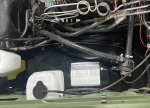
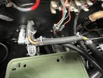
Decided to finish installing & plumbing the electric fuel pump. I used a Carter P4600HP which is a 12v, 50 gallon/hour 4.5-8 psi frame-mounted pump. I wanted to use a 24v but the P4603HD was nowhere to be found. The 12v model pulls 10 amps and will be ignition/relay-wired. Not knowing how much fuel the supercharged P400 will drink in WOT, I reached out to Bob Reynolds at Carter Technical Service for his opinion. Bob ran calculations for diesel fuel consumption in a 6.5 GM engine producing 300 HP and recommended the P4600HP. He indicated that the P4600HP might be slightly over-sized, but the fact that the fuel return line from the engine to the tank is a full 1/4" line, means that any excess fuel not needed by the engine will simply be returned to the tank. This is another reason why I incorporated a fuel pressure gauge in the custom gauge panel, so I can make sure the engine is not fuel-starved.

While I was under the truck and in the process of mounting the fuel pump to the frame, I decided to also incorporate a filter between the twin tank valve and the pump. After spending hours evaluating numerous diesel fuel filters online and at Summit, I chose a HENKYO R12T 10-micron, which is also a frame-mounted unit. The R12T also features a water separator with a clear bowl to catch any water incoming from station fuel. Both filter and water bowl are spin-on/off and the bowl has a handy threaded drain cock knob which can be operated with gloves on. In order to provide a straight-through route for the forthcoming 3" exhaust, I mounted the R12T on the cross-member under the front of the bed, between the exhaust route and the forthcoming new driveshaft route. New 3/8" rubber fuel line was used but I wanted to re-use the OEM hose clamps for nostalgic reasons. Mounting the P4600HP fuel pump on the frame caused a complication of hose routing, so I cut-off the 3/8" hard line from the engine just forward of the pump and installed a 3/8" compression x 3/8" hose barb adapter onto the hard line to connect the rubber hose. Everything worked perfectly. Before I crank the engine for the first time, I will disconnect the 4AN hose running to the fuel isolator on the firewall and energize the pump with a battery to pre-prime the system but also to run a quart or so through the filter & pump & lines to clear any small particles or debris left over from the manufacturing processes. More updates coming soon.

View attachment 951721


View attachment 951722
Missing altitude, attitude, roll, ambient temp, barometer, and timepiece.
 

Sharecropper

Well-known member
Steel Soldiers Supporter
1,938
1,234
113
Location
Paris KY
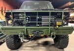
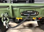
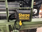
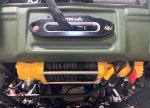
Made a little more progress. Got the Sherpa 24v 17,000 lb winch mounted and the bumper & grille guard back on. Had to fabricate a couple steel brackets for the grille guard to mount the control box. The winch came with the wireless remote so I mounted the transmitter immediately behind the control box on the core support so the cable can stay plugged in. The behind-the-bumper winch mount by Engineered Vintage worked great, but it was a bear getting the two bottom bumper bolts installed & torqued. I decided to convert the 24v slave port to a 12v port and plan to rig-up a custom set of jumper cables so I won't have to open my hood to jump-start these idiots that live around me. The slave wiring will tap off the rear Hawker battery. Will be reinstalling the doors & front fenders next, then batteries and a few things and then will be ready to add fluids and see if it will crank.

IMG_1394.jpgIMG_1395.jpgIMG_1396.jpgIMG_1397.jpg
 

1love

Active member
138
137
43
Location
CA
Made a little more progress. Got the Sherpa 24v 17,000 lb winch mounted and the bumper & grille guard back on. Had to fabricate a couple steel brackets for the grille guard to mount the control box. The winch came with the wireless remote so I mounted the transmitter immediately behind the control box on the core support so the cable can stay plugged in. The behind-the-bumper winch mount by Engineered Vintage worked great, but it was a bear getting the two bottom bumper bolts installed & torqued. I decided to convert the 24v slave port to a 12v port and plan to rig-up a custom set of jumper cables so I won't have to open my hood to jump-start these idiots that live around me. The slave wiring will tap off the rear Hawker battery. Will be reinstalling the doors & front fenders next, then batteries and a few things and then will be ready to add fluids and see if it will crank.

View attachment 952261View attachment 952262View attachment 952263View attachment 952264

ITS SO PERFECT!
 

bl71236

Active member
82
104
33
Location
Corsicana, TX
OK folks, here's my first question -

Would it be possible to completely abandon the current instrument cluster for a new custom unit comprised of all new M38A3 gauges?

I can design and build a replacement gauge mounting face fabricated from 1/8" aluminum, correctly shaped and bent to fit precisely as the existing black plastic does. I would need to engineer a top mount structure for this new face, however I have already got that figured out. The M38A3 gauges would simply mount into the holes milled into the new aluminum face. I would set this up in AutoCad and mill the shape and openings in the mounting face on a CNC router. The aluminum mounting face would then be bead blasted and painted 383. What do yall think? is it possible? What problems or obstacles are there to overcome?

I would want a large diameter Speedometer and Tach mounted side-by-side in the middle, and smaller diameter fuel, temp, oil pressure, volt meters (2), and the 24-volt meter mounted on either side. The heater control can be fastened to te back side of the new face, and the BO lights and headlight switch would simply stick through the way they do now. There would be some extra room where a radio would normally be located, however I would use this area for push-button glow plug switching and other switches.

All of the new gauges would have to be hooked up manually, which is part of the goal anyway.

Any comments?
Take a look at my solution. I made aluminium overlays.
 

Sharecropper

Well-known member
Steel Soldiers Supporter
1,938
1,234
113
Location
Paris KY
Take a look at my solution. I made aluminium overlays.
Hmmmm...... It seems you have replied to my post from July 2010. A lot has happened in the 15 years since.

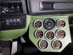
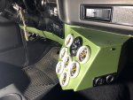
I designed, engineered, fabricated, installed, and hooked-up my custom gauge panel. Thanks for your reply, however I am miles ahead of you on my rebuild. I hope you will read through the entire thread and maybe learn from my mistakes.


IMG_5089.jpgIMG_5091.jpg
 

bl71236

Active member
82
104
33
Location
Corsicana, TX
Hmmmm...... It seems you have replied to my post from July 2010. A lot has happened in the 15 years since.

I designed, engineered, fabricated, installed, and hooked-up my custom gauge panel. Thanks for your reply, however I am miles ahead of you on my rebuild. I hope you will read through the entire thread and maybe learn from my mistakes.


View attachment 953320View attachment 953321
Very Nice! Sorry,i forget to check dates sometimes.
 

Sharecropper

Well-known member
Steel Soldiers Supporter
1,938
1,234
113
Location
Paris KY
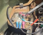
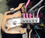
I've owned, worked on, and enjoyed square-body trucks for as long as there have been square-body trucks. But I have never cared for GM's design of the ground buss under the dash attached to the emergency brake frame. Today I am finishing up the cab wiring in preparation of dash & seat reinstallation, and decided to do something about that darn ground buss. The original GM design consisted of a thin bracket with six prongs, onto which 12v ground wires with female spade connectors can be attached. The problem has always been the eventual looseness developed in the spade connectors, resulting in the connectors coming loose and becoming unattached to the prong. Thinking through how I could improve the original design and provide more secure ground connections, I came up with fabricating a new buss with 8-32 hex-head screws & star washers for each ground wire. I had some 3/4" x 3/4" square steel tube stock in my inventory, so I cut a piece 3-1/2" long and then cut three sides off 1-1/4" from one end to form a flat bar with a hole drilled in it to attach back into the same location. I drilled & tapped ten holes, five on the side and five on the bottom, to provide plenty of attachment for future accessories. Here's what the before & after product looks like -

IMG_1404.jpg
IMG_1407.jpg
 

1love

Active member
138
137
43
Location
CA
I've owned, worked on, and enjoyed square-body trucks for as long as there have been square-body trucks. But I have never cared for GM's design of the ground buss under the dash attached to the emergency brake frame. Today I am finishing up the cab wiring in preparation of dash & seat reinstallation, and decided to do something about that darn ground buss. The original GM design consisted of a thin bracket with six prongs, onto which 12v ground wires with female spade connectors can be attached. The problem has always been the eventual looseness developed in the spade connectors, resulting in the connectors coming loose and becoming unattached to the prong. Thinking through how I could improve the original design and provide more secure ground connections, I came up with fabricating a new buss with 8-32 hex-head screws & star washers for each ground wire. I had some 3/4" x 3/4" square steel tube stock in my inventory, so I cut a piece 3-1/2" long and then cut three sides off 1-1/4" from one end to form a flat bar with a hole drilled in it to attach back into the same location. I drilled & tapped ten holes, five on the side and five on the bottom, to provide plenty of attachment for future accessories. Here's what the before & after product looks like -

View attachment 953469
View attachment 953470
Thanks! Looks like I'll be doing the same mod!
 

Sharecropper

Well-known member
Steel Soldiers Supporter
1,938
1,234
113
Location
Paris KY
Thanks! Looks like I'll be doing the same mod!

Make sure you clean the rust off the brake frame prior to installing the new ground buss, thereby allowing additional grounding capability through the back side of the new buss bracket. It's a bear to get to, so I recommend pulling out the instrument panel for easy access. While you have it out you can clean the gauge bulb sockets and replace any that needs replacing. I actually sprayed the inside of my housing with silver reflective paint and replaced the three (3) dash light illumination bulbs with bright LED bulbs. What a difference! No need to replace any of the other bulbs, unless you just want to or not working. I am attaching a great guide which explains the instrument cluster better than any I have ever seen. The three (3) dash light illumination bulbs are identified on page 5 & 6 of the document.

Hope this helps.
 

Attachments

1love

Active member
138
137
43
Location
CA
Make sure you clean the rust off the brake frame prior to installing the new ground buss, thereby allowing additional grounding capability through the back side of the new buss bracket. It's a bear to get to, so I recommend pulling out the instrument panel for easy access. While you have it out you can clean the gauge bulb sockets and replace any that needs replacing. I actually sprayed the inside of my housing with silver reflective paint and replaced the three (3) dash light illumination bulbs with bright LED bulbs. What a difference! No need to replace any of the other bulbs, unless you just want to or not working. I am attaching a great guide which explains the instrument cluster better than any I have ever seen. The three (3) dash light illumination bulbs are identified on page 5 & 6 of the document.

Hope this helps.
Nice thank you for this!!! PDF is gold!
 
Top
AdBlock Detected

We get it, advertisements are annoying!

Sure, ad-blocking software does a great job at blocking ads, but it also blocks useful features of our website like our supporting vendors. Their ads help keep Steel Soldiers going. Please consider disabling your ad blockers for the site. Thanks!

I've Disabled AdBlock
No Thanks