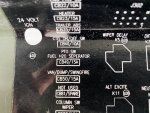
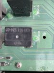
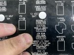
I connected the tachometer (ISSPRO R8530M the same one that Sean Fillner installed) to the PX26 (Frequency Divider) terminal where cables 3083 and 1444 from the Engine Speed Magnetic Pickup are connected but to no avail. I have however seen that the connections for the original tachometer (in the center of the dashboard) connect to terminals 1546-1550 from terminal P913 (?).
How can I get it to work?
Wire 1444 is the + signal from the sensor, and wire 3083 is the - signal from the magnetic pickup and is tied/referenced to ground at the freq divider connector. At the freq divider, wire 1444 is spliced to wire 1550 for the run over to the center dash Where it is also the + signal. I think the drawing may be wrong on specifying 1546 as the other wire/- signal in the center dash, as 1546 is 24V DC instrument power from CB 77.
That 24V DC power is fed to instrunments like oil pressure or engine temperature that feed it thru the meter coil then down to a pressure or temperature sensor that provide a varying resistance to ground based on the pressure or temperature sensed. This changes current flow thru the meter coil and the needle position To reflect what the sensor is seeing. The center tach does need power to function but for tack sense it should be looking at signal + and -(ground).
The engine RPM sensor is basically a small electric generator(coil of wire around a magnetic core). As the ring gear teeth pass in close proximity to the core a series of small voltage pulses are generated. If you connected the tach sense wires to this and 24V it would not work and might damage the tach or if 24V somehow got fed back thru the sensor which is tied to ground, it might burn up the pickup coil in the RPM sensor...
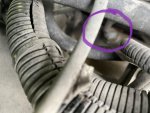
As for making yours work, my first question is do you have a signal coming from the RPM sensor? Since the sensor is a generator, you can check for this signal with a volt meter set for AC volts. At the freq divider, connect the meter leads to wire 1444 and 3083. With the engine running, see if you have any voltage there. I am not sure what the cat is supposed to be as I have not checked mine. the one on my tractor puts out 5 volts... If you do not see an AC voltage there, shut off the engine, unplug the freq divider connector and switch the meter to ohms and look for a circuit down thru the pickup on those same wires, 1444 to 3083. If you don’t have a circuit, check the connector at the sensor(drivers side bellhousing near the top and perform the same tests. The sensor coil should have 1440 ohms of resistance.
if you do have a voltage, it may be too weak. If the sensor has been unscrewed, the farther the head gets from the ring gear teeth the weaker the signal. What also sometimes happens is metal shavings from the ring gear collect on the magnetic head of the sensor and can disrupt/weaken the output. They also sometimes get loose and screw themselves in and the ring gear destroys the head of the sensor. You can unscrew it to check it and clean it. Before you unscrew it loosen the lock nut and see how far in it will turn before it touches the ring gear, then remove it to clean and inspect. screw it all the way back in till it touches, and then back it out 2 full turns... they are pretty simple, if they have proper resistance and are clean and positioned properly you should get AC voltage with the engine running.
if you get voltage at the sensor, but not when everything is plugged back in, it could also be the freq divider. It is not really a divider, it is an isolation amp, so STE can sample the sensor without loading it down so much that it won’t drive the installed tach... if it was shorted it might load the signal down.
The freq divider’s sole purpose is to feed STE, so you can simply remove it. You can also pull that black plastic box and the STE connector from under the dash. 3 connectors and it all comes right out...


