• Steel Soldiers now has a few new forums, read more about it at: New Munitions Forums!

  • Microsoft MSN, Live, Hotmail, Outlook email users may not be receiving emails. We are working to resolve this issue. Please add support@steelsoldiers.com to your trusted contacts.


M1008 Build

DIVE DIVE

Well-known member
Steel Soldiers Supporter
217
778
93
Location
Chesapeake, VA
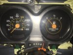
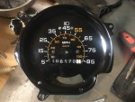
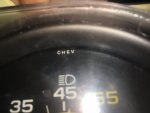
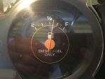
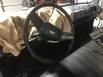
Got the instrument panel finished up today. I had to replace the speedometer because the one that was there wasn’t responding. Come to find out it was an aftermarket one from china. I thought it looked weird but couldn’t figure out what it was, then I realized that it had an extra number, so you could read out 6 digits, not counting the 1/10 mile. Anyways, it’s trash. Replaced with an original from a buddy of mine down the street (freebie) who replaced his with a digital.

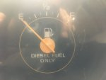
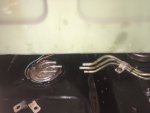
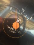
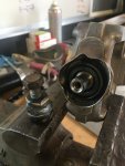
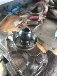
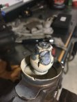
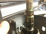
Got the fuel gage working too. I read a bunch of different people stating that the sending unit was 0-90 ohms. I exercised this unit after cleaning it up, and worked the sweeper for the variable resistor until it consistently read. I was able to get it to read about 9 ohms empty and about 104 ohms full. With those numbers it is dead on the empty mark and just over the full mark.
So at this point the instrument panel is completely operational.
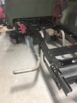
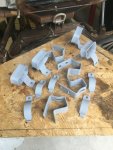
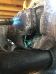
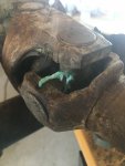
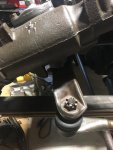
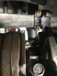
I was also able to get the exhaust installed today and zip tied up since I haven’t finished painting the hangers yet.
 

Attachments

DIVE DIVE

Well-known member
Steel Soldiers Supporter
217
778
93
Location
Chesapeake, VA
Here is a pic of the fuel tank o-ring seal and metal ring part number. Also I took a picture of that Chinese speedo. Notice the extra digit and something else I noticed: look closely at the original gage. It says “CHEV” at the very top. It’s hard to see in the pic because this one is installed and covered by the reflector cover slightly. The aftermarket one does not have this marking.
 

Attachments

DIVE DIVE

Well-known member
Steel Soldiers Supporter
217
778
93
Location
Chesapeake, VA
Attacked the front driveshaft today. Made a bunch of little blue snakes. It’s like those black snake things you used to get at the firework stand lol. Burned out the factory u-joints and Spicers will be going back in just like the originals, except with grease fittings.
Looks like a war zone at the work bench where I beat the driveshaft into submission.
I put 5 gallons of diesel in the fuel tank today and that’s where the needle went. Seems close to where it should be for a “20 gallon” tank.
 

Attachments

DIVE DIVE

Well-known member
Steel Soldiers Supporter
217
778
93
Location
Chesapeake, VA
Bad news. In hindsight I should have just left it alone because there wasn’t anything wrong with it. I was replacing the old ball joint in the center of the double cardan joint on the front driveshaft. There is a special tool for this job which I don’t have so I welded a nut onto the old ball and just basically used it as a jacking bolt to get it off, it worked fine, no issues.

Then I prepped the joint for reassembly by straightening the dust shield, which was all bent up from the disassembly process, and cleaning the ball receiver. For whatever reason, when the ball got about half way down, it got stuck (really stuck) and now I can get it off. I even went as far as to sacrifice the ball by welding a nut on the new one to repeat the original process and it’s not moving. Not good. So now I need a new driveshaft and I’m out the 50 dollar rebuild kit (which was a spare I had laying around).

Not a great story. So now I’m leaving it alone to think of other ideas, but unfortunately the only viable option is replacement of the driveshaft.
 

Attachments

ezgn

Well-known member
Steel Soldiers Supporter
650
1,039
93
Location
Lake Elsinore Ca.
Bad news. In hindsight I should have just left it alone because there wasn’t anything wrong with it. I was replacing the old ball joint in the center of the double cardan joint on the front driveshaft. There is a special tool for this job which I don’t have so I welded a nut onto the old ball and just basically used it as a jacking bolt to get it off, it worked fine, no issues.

Then I prepped the joint for reassembly by straightening the dust shield, which was all bent up from the disassembly process, and cleaning the ball receiver. For whatever reason, when the ball got about half way down, it got stuck (really stuck) and now I can get it off. I even went as far as to sacrifice the ball by welding a nut on the new one to repeat the original process and it’s not moving. Not good. So now I need a new driveshaft and I’m out the 50 dollar rebuild kit (which was a spare I had laying around).

Not a great story. So now I’m leaving it alone to think of other ideas, but unfortunately the only viable option is replacement of the driveshaft.
You're doing a great job on everything you have done so far. Sometimes the unexpected happens. Push forward, put it behind you and move on.
 

DIVE DIVE

Well-known member
Steel Soldiers Supporter
217
778
93
Location
Chesapeake, VA
Got the drag link rebuilt and cleaned up and also the steering shaft disassembled and re-greased. These won’t be getting paint, just a light coat of oil.
That picture of the grease boot shows a clump of grease that I pulled out of it. Crazy, it was like clay. The other one was still grease like.
 

Attachments

ezgn

Well-known member
Steel Soldiers Supporter
650
1,039
93
Location
Lake Elsinore Ca.
10 gallons. Theoretically should read 1/2. Not a good trend that 5 gallons indicated less than 1/4 and 10 gallons indicates greater than 1/2 but we’ll see what happens.
I'm not sure you can use the gauge as an accurate assessment of the tank level. When a tank is completely full, at least on my gauge, the marker gauge measures well past the last full point mark on the gauge.
 

Mullaney

Well-known member
Steel Soldiers Supporter
Supporting Vendor
7,347
19,032
113
Location
Charlotte NC
I'm not sure you can use the gauge as an accurate assessment of the tank level. When a tank is completely full, at least on my gauge, the marker gauge measures well past the last full point mark on the gauge.
.
Agreed! On my 83 (plain Chevy truck) pumped full of gas, I could drive for a week before the needle moved off of full. Not a long ride to work, so that seemed reasonable to me.

@DIVE DIVE, I think the measurements that you have done are pretty useful. Now you know that at a Quarter Tank - you have roughly 5 gallons. Multiply that by your MPG and you know when to start hunting for fuel.
 

ezgn

Well-known member
Steel Soldiers Supporter
650
1,039
93
Location
Lake Elsinore Ca.
.
Agreed! On my 83 (plain Chevy truck) pumped full of gas, I could drive for a week before the needle moved off of full. Not a long ride to work, so that seemed reasonable to me.

@DIVE DIVE, I think the measurements that you have done are pretty useful. Now you know that at a Quarter Tank - you have roughly 5 gallons. Multiply that by your MPG and you know when to start hunting for fuel.
That is spot on. I never even thought about that. Good thinking Man.
 

DIVE DIVE

Well-known member
Steel Soldiers Supporter
217
778
93
Location
Chesapeake, VA
I’m having a hard time understanding the steering wheel straightening process. On this particular setup there is only one way to attach the steering wheel to the steering column top, one way to attach the intermediate shaft to the steering column bottom, and one way to attach the intermediate shaft “rag joint” to the steering gear. One could make an argument that the intermediate shaft to steering column bottom joint could be installed in two ways, but it is only meant to be installed one particular way it seems to me (regardless, only two options). So setting the steering gear in the centered position then results in a crooked steering wheel. Working backwards, beginning with a straight steering wheel, results in unequal travel left to right. Nothing in the tech manuals, and there are many variations of this steering column setup, so online searches have been fruitless thus far.
Can anyone help me understand this?
The only thing I can think is that the steering gear will have to be in whatever position that ends up being in once the steering wheel is straight then the drag link is adjusted to straighten the wheels. This seems odd to me but I guess it will work as long as the steering knuckle hits the mechanical stop bolt prior to the steering box hitting it’s stopping point mid-turn, which would be undesirable. An easy solution is to just make the steering gear splined over its entire input shaft vice having the flat on it but that isn’t the case for some reason.
 

Attachments

Mullaney

Well-known member
Steel Soldiers Supporter
Supporting Vendor
7,347
19,032
113
Location
Charlotte NC
I’m having a hard time understanding the steering wheel straightening process. On this particular setup there is only one way to attach the steering wheel to the steering column top, one way to attach the intermediate shaft to the steering column bottom, and one way to attach the intermediate shaft “rag joint” to the steering gear. One could make an argument that the intermediate shaft to steering column bottom joint could be installed in two ways, but it is only meant to be installed one particular way it seems to me (regardless, only two options). So setting the steering gear in the centered position then results in a crooked steering wheel. Working backwards, beginning with a straight steering wheel, results in unequal travel left to right. Nothing in the tech manuals, and there are many variations of this steering column setup, so online searches have been fruitless thus far.
Can anyone help me understand this?
The only thing I can think is that the steering gear will have to be in whatever position that ends up being in once the steering wheel is straight then the drag link is adjusted to straighten the wheels. This seems odd to me but I guess it will work as long as the steering knuckle hits the mechanical stop bolt prior to the steering box hitting it’s stopping point mid-turn, which would be undesirable. An easy solution is to just make the steering gear splined over its entire input shaft vice having the flat on it but that isn’t the case for some reason.
.
Not the all knowing here for sure, but WHAT IF:

For example, the steering wheel points at 2 o'clock when the truck is driving a straight line. The front end alignment is correct. Truck stays straight with no uneven wear on the tires. Steering wheel only fits one way? OR maybe just remove it and put it back straight, or do I...

To get the steering wheel straight you have to adjust the tie rod sleeves equally. If the wheel is cocked to the left while going straight - you need to lengthen the left side and shorten the right side by the same exact amount. All it takes is loosening the 2 nut/bolts on the sleeve and turn.

That should help with "more left than right" turning ability too.
 

DIVE DIVE

Well-known member
Steel Soldiers Supporter
217
778
93
Location
Chesapeake, VA
.
Not the all knowing here for sure, but WHAT IF:

For example, the steering wheel points at 2 o'clock when the truck is driving a straight line. The front end alignment is correct. Truck stays straight with no uneven wear on the tires. Steering wheel only fits one way? OR maybe just remove it and put it back straight, or do I...

To get the steering wheel straight you have to adjust the tie rod sleeves equally. If the wheel is cocked to the left while going straight - you need to lengthen the left side and shorten the right side by the same exact amount. All it takes is loosening the 2 nut/bolts on the sleeve and turn.

That should help with "more left than right" turning ability too.
The adjusting sleeves won’t change the position of the steering gear (pitman arm) relative to the steering wheel position.
What I need to do is get the front end off the ground and cycle the steering to ensure that if I straighten the wheel using the drag link adjustment that it won’t bind the steering box, and it hits the mechanical stops first, when at full steer. I assume this will be the case since I don’t see any other method of adjustment to straighten the wheel.
That being said, straight line driving is separate from off camber driving in an off road condition, which could then lead to the inability to turn the steering wheel, with the tires straight, if the suspension is at full stuff in one side and full droop on the other due to the geometry changing in the steering linkage.

It just confuses me why they made the input shaft to the steering gear with a flat on it, vice the shaft being splined 360 degrees to allow clocking the steering shaft, since there is no other method of adjustment.
 

Mullaney

Well-known member
Steel Soldiers Supporter
Supporting Vendor
7,347
19,032
113
Location
Charlotte NC
The adjusting sleeves won’t change the position of the steering gear (pitman arm) relative to the steering wheel position.
What I need to do is get the front end off the ground and cycle the steering to ensure that if I straighten the wheel using the drag link adjustment that it won’t bind the steering box, and it hits the mechanical stops first, when at full steer. I assume this will be the case since I don’t see any other method of adjustment to straighten the wheel.
That being said, straight line driving is separate from off camber driving in an off road condition, which could then lead to the inability to turn the steering wheel, with the tires straight, if the suspension is at full stuff in one side and full droop on the other due to the geometry changing in the steering linkage.

It just confuses me why they made the input shaft to the steering gear with a flat on it, vice the shaft being splined 360 degrees to allow clocking the steering shaft, since there is no other method of adjustment.
.
Agreed. Wasn't suggesting anything about caster or camber or alignment. Just moving the wheel left or right to center it up. Making the left side longer - or the right side longer (sorry, I don't know which way to go) will absolutely turn that steering wheel. Obviously it will get better or worse.

You loosen the locks and turn the sleeves together. OR half turn the on the left a half turn, then the right and so on. Maybe if you get a "Soldier2" in the seat watching the wheel, you can do less work before going the wrong direction. Maybe?
 

DIVE DIVE

Well-known member
Steel Soldiers Supporter
217
778
93
Location
Chesapeake, VA
.
Agreed. Wasn't suggesting anything about caster or camber or alignment. Just moving the wheel left or right to center it up. Making the left side longer - or the right side longer (sorry, I don't know which way to go) will absolutely turn that steering wheel. Obviously it will get better or worse.

You loosen the locks and turn the sleeves together. OR half turn the on the left a half turn, then the right and so on. Maybe if you get a "Soldier2" in the seat watching the wheel, you can do less work before going the wrong direction. Maybe?
Yes, sir I understand what you are saying. My concern is: the reason that the process you described above changes the steering wheel position is because it changes the pitman arm position. This means that I will be sacrificing steering ability in one direction, and gaining that ability in the other direction (again, if the steering knuckles don’t hit the stops before the box reaches its limits) because the pitman arm is no longer centered in the steering box.

It is an odd design, that could be easily remedied by a uniformly splined input shaft on the steering gear instead of making the input shaft only fit on one way, that’s all I’m saying :)
 

WWRD99

Well-known member
Steel Soldiers Supporter
883
1,349
93
Location
York Pa
I’m having a hard time understanding the steering wheel straightening process. On this particular setup there is only one way to attach the steering wheel to the steering column top, one way to attach the intermediate shaft to the steering column bottom, and one way to attach the intermediate shaft “rag joint” to the steering gear. One could make an argument that the intermediate shaft to steering column bottom joint could be installed in two ways, but it is only meant to be installed one particular way it seems to me (regardless, only two options). So setting the steering gear in the centered position then results in a crooked steering wheel. Working backwards, beginning with a straight steering wheel, results in unequal travel left to right. Nothing in the tech manuals, and there are many variations of this steering column setup, so online searches have been fruitless thus far.
Can anyone help me understand this?
The only thing I can think is that the steering gear will have to be in whatever position that ends up being in once the steering wheel is straight then the drag link is adjusted to straighten the wheels. This seems odd to me but I guess it will work as long as the steering knuckle hits the mechanical stop bolt prior to the steering box hitting it’s stopping point mid-turn, which would be undesirable. An easy solution is to just make the steering gear splined over its entire input shaft vice having the flat on it but that isn’t the case for some reason.
When you do an alignment the steering wheel is locked to the straight position...then once the wheels have been aligned the steering wheel will be straight...you align the truck to the steering wheel not the wheel to the truck...usually when I do an alignment on something that has been taken apart or really off I'll adjust the center hold on the steering wheel to make sure it is straight once I'm done...I've had a few where I thought I had it perfect only to find that it's off just a tiny bit which drives me nuts so that's why i do the wheel 2 times...the next battle is typically tire pull but that's mostly cars and not trucks as much.
 

Sharecropper

Well-known member
Steel Soldiers Supporter
1,814
942
113
Location
Paris KY
I'm just now getting into this conversation so I will provide my comments:

The adjustable pitman that connects the steering gear arm to the steering knuckle on the wheel is the method of adjusting the steering wheel position. It is simple - the nuts on the threaded sleeve assembly (#12 in Figure 128 of 34-P) should be loosened and then the sleeve assembly itself should be turned one way or the other, with a pipe wrench or vice grips, to lengthen or shorten the distance between the steering gear arm and the wheel knuckle. It has nothing to do with camber or caster or the adjustable wheel-turn lock bolts. It only takes a slight turn to see a dramatic change in the steering wheel position.

Hope this helps.
 
Top
AdBlock Detected

We get it, advertisements are annoying!

Sure, ad-blocking software does a great job at blocking ads, but it also blocks useful features of our website like our supporting vendors. Their ads help keep Steel Soldiers going. Please consider disabling your ad blockers for the site. Thanks!

I've Disabled AdBlock
No Thanks