• Steel Soldiers now has a few new forums, read more about it at: New Munitions Forums!

  • Microsoft MSN, Live, Hotmail, Outlook email users may not be receiving emails. We are working to resolve this issue. Please add support@steelsoldiers.com to your trusted contacts.

M925 winch info needed

Richmond

New member
17
1
0
Location
KY
I have a project that I'm using a winch set up from a m925 on. I have searched and searched for info on a few things with no luck. such as,

What is the ratio or percentage of the pto used or its model# ?

A hydraulic circuit diagram, (I'm not sure which lines go where on the control valve) ?

If anyone knows or has any links that could help that would be great, thanks
 

M35A2-AZ

Well-known member
Steel Soldiers Supporter
3,222
392
83
Location
Tonopah, AZ
I just install a winch on my M929.
I do know they use an Open Center for the valve.
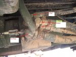
Here is a pics of the valve that was on the M929 before I took it off.
The hose hanging down is from the battery box.
 

Attachments

Richmond

New member
17
1
0
Location
KY
Thank you for the picture M35A2-AZ, thats exactly what i was trying to verify. thats one question answered now i just need to find the ratio for the pto or a model number so I can try to look up the specs on them.
 

tobyS

Well-known member
4,832
833
113
Location
IN
What are you asking? Are you trying to design a hydraulic circuit using something you already have for a pump or valve that will operate the winch motor? I can give you volume and flow from the hydraulic motor but it seems that you are asking about the hose to valve connections instead.

On a single spool valve, there are in and out ports and a and b. The pressure line from the pump goes in and line to tank connects to out. a and b connect to the motor and if you get it wrong (your control lever backward), just reverse them. Clean your valve off to see the markings.

Something is wrong in the picture of the valve and the labels, I think. It shows the return line as the pump line. The pump is the smaller high pressure line and the largest one is the return to tank...just backward of the labels.
 
Last edited:

porkysplace

Well-known member
Steel Soldiers Supporter
9,604
1,493
113
Location
mid- michigan
Thank you for the picture M35A2-AZ, thats exactly what i was trying to verify. thats one question answered now i just need to find the ratio for the pto or a model number so I can try to look up the specs on them.
Get the part number from the parts TM and then run the part number through parts-target to get the model/manufacturer info.
 

Richmond

New member
17
1
0
Location
KY
I have the whole winch set up, motor, pump, etc. I'm just missing the pto that mounts on the trans. I need to know the ratio of the pto. they range from 25% to 150% of engine speed. I cant find any info on the pto they used originally, make, model, or any specs. the picture that M35A2 posted is correct, the larger hose is the supply from the pump to the spool valve. thanks
 

rhurey

Member
Steel Soldiers Supporter
737
14
18
Location
Bothell, WA
Well, from my wet kit the pressure line was a J-16 and the return was a J-12. All going into a valve w/ -10 ports. The bottom is from the pump. I do recall thinking how... un-optimal... it was for the pressure line to be the lowest spot on the vehicle.
 

Richmond

New member
17
1
0
Location
KY
I think you need to look at your truck again, tobyS. the large port on the spool valve is the power from pump, I appreciate the link to C&C but he doesn't have a part number listed so I still cant get the ratio from it. It shows the manufacture and series but they have multiple ratios available.
 

tobyS

Well-known member
4,832
833
113
Location
IN

from M16ty prior post
"I think the pump is rated at 14gpm @ 1,000 rpm. The PTO turns right at 2,000 rpm at governed speed so that gives you right at 24-26gpm.
Here's a link that tells you how to read the numbers- http://www.google.com/url?sa=t&rct=j...,d.eWU&cad=rja

Still, it does not give pto ratio if diffferent from 1/1

I sold the truck so cannot look. I design hydraulic systems for sawmills, open center and closed for a living, but I'll take your word they are backward, it is the government.


Last edited:

M35A2-AZ

Well-known member
Steel Soldiers Supporter
3,222
392
83
Location
Tonopah, AZ
Something is wrong in the picture of the valve and the labels, I think. It shows the return line as the pump line. The pump is the smaller high pressure line and the largest one is the return to tank...just backward of the labels.
The picture is right, the large line is from the pump.
 

tobyS

Well-known member
4,832
833
113
Location
IN
Is there a reason?

It appears a 3/4 line will flow 27 gpm, which is the pumps capacity. If you have the hose on hand and don't have to buy it, then it makes sense, but if I were engineering it, I'd spend money elsewhere where it is needed. Part of the problem I see with being tight is that the size is not proportional to the flow, it takes a lot more space for a 1" than a 3/4 and costs twice as much if you are purchasing hose and fittings. But if you have them already, go for it.


FLOW CAPACITIES OF HYDRAULIC LINES
Recommended Maximum for PRESSURE LINES
(Based on Velocity of 20 Ft/Sec)
HOSE SIZEFLOW – GPMPIPE SIZEFLOW – GPM
1/43.51/46.5
3/873/812
1/2121/219
3/4273/433
148156
1 1/4751 1/493
INCREASE SIZE IF:

  • Oil Viscosity exceeds 150 SSU (SAE 10)
  • Oil is cold
  • Suction lines are over 5 ft. long
  • Pressure lines are over 15 ft. long
  • There are multiple fittings or obstructions in line
 

M35A2-AZ

Well-known member
Steel Soldiers Supporter
3,222
392
83
Location
Tonopah, AZ
tobyS, I do not know why it is like that, but that is the way the Military trucks are. It maybe due to the open center????

I like the flow rate table.
 

tobyS

Well-known member
4,832
833
113
Location
IN
I guess it comes down to... if one is buying the materials or not. Spending tax dollars (military) is entirely different than spending ones own. It will cost 2x more for 1" than 3/4".

So the military uses 1".
 

M35A2-AZ

Well-known member
Steel Soldiers Supporter
3,222
392
83
Location
Tonopah, AZ
I guess it comes down to... if one is buying the materials or not. Spending tax dollars (military) is entirely different than spending ones own. It will cost 2x more for 1" than 3/4".

So the military uses 1".
You are right there. The Line from the pump was 1" and the line to the tank was 3/4"( I think) and the lines to the winch are 3/4".
 

rhurey

Member
Steel Soldiers Supporter
737
14
18
Location
Bothell, WA
I guess it comes down to... if one is buying the materials or not. Spending tax dollars (military) is entirely different than spending ones own. It will cost 2x more for 1" than 3/4".

So the military uses 1".
And they hard pipe 1/2 of it.

winch_pump.jpg
 
161
2
18
Location
Argyle MI
So i know this is an old thread but i have a m925 and im putting a hoist under the bed. It came with a tank that has a built in pump so im thinking of running that pump with a hydraulic motor of the oribjginal pump. A little redundant i know but it has the right valve and everything all in one unit. So my question is can i splice into the pump pressure line and feed the motor first then go to the valve? Or vice versa?

Sent from my SAMSUNG-SM-G890A using Tapatalk
 

tobyS

Well-known member
4,832
833
113
Location
IN
You need a through feed valve that is just as large as the existing valve or a 2 section valve... and larger capacity tank. Post pictures of what you have.
 
Top
AdBlock Detected

We get it, advertisements are annoying!

Sure, ad-blocking software does a great job at blocking ads, but it also blocks useful features of our website like our supporting vendors. Their ads help keep Steel Soldiers going. Please consider disabling your ad blockers for the site. Thanks!

I've Disabled AdBlock
No Thanks