• Steel Soldiers now has a few new forums, read more about it at: New Munitions Forums!

  • Microsoft MSN, Live, Hotmail, Outlook email users may not be receiving emails. We are working to resolve this issue. Please add support@steelsoldiers.com to your trusted contacts.

MEP-1050 Fault Code 3665

peapvp

Well-known member
Steel Soldiers Supporter
1,248
1,571
113
Location
Basehor, KS
@peapvp - Thank you for your reply. Do you mean I should test all wiring before reconnecting this cut / broken wire shown in my above photos?

Do you think this cut / broken wire could be the reason I have the 3665 fault code?
I am certain that this wire and the burnt wire are just the tip of the iceberg.
And yes all wiring issues known and unknown at this point are causing the error(s)
 

BadAmish

Member
32
44
18
Location
Grants Pass, Oregon
@peapvp & @Guyfang - Thank you. I was able to spend some time last evening looking into the wiring and control panel. Here are some photos of what I found:

The wire that we've been referring to as burned appears on closer inspection to be gnawed or chewed and / or possible just rough-handled. I'm sorry these photos are blurry. I took them with my phone and I thought they looked better on the little phone screen and it wasn't until I closed everything back up and reviewed them on a computer monitor that I could see they are kind of poor quality.

mep-1050-damaged-wire-1.jpg

mep-1050-damaged-wire-2.jpg

mep-1050-damaged-wire-3.jpg

What do you folks think? If it was burned, wouldn't it be the whole wire and not just some spots? Regardless, I understand that this needs repairing or replacing. Speaking of repairing or replacing, what is recommended? Do I source a replacement wire or fabricate one myself?

I removed the connector with the broken / cut wire P1-SHLD1 wire and look what I found:

mep-1050-bent-pin-s-connector-ji.jpg

I straightened that pin, I think it is the "S" pin on the J1 connector.

I also re-attached the previously broken wire to see if any errors went away. They did not.

I took some somewhat better photos of the screens. In a few you may notice that the "Battle Short" mode is active and that is because I was testing to see if indeed that switch was working.

One thing I noticed is that when I power up the MEP-1050 initially after re-attaching the batteries the oil pressure indicator is lit - not greyed out - and then goes greyed out after about 3-5 seconds.

mep-1050-oil-indicator-on.jpg

mep-1050-oil-indicator-off.jpg

Here are some other control screen photos including the one with the firmware versions. I do not know if firmware is a thing that gets updated at all or not on these generators.

mep-1050-oil-rifle-pressure-screen.jpg

What is engine oil rifle pressure? That is a strange term to me.

mep-1050-fuel-level-low-screen.jpg

I knew the fuel level was low, but I was sure that there was some in the tank. Is there a minimum amount I should have for testing / repairing this unit?

mep-1050-coolant-temp-1-sensor-high-voltage.jpg

Engine coolant temp 1 sensor cut high voltage. Voltage above normal or shorted to high source. I guess this says it.

mep-1050-firmware-screen.jpg
 

Attachments

BadAmish

Member
32
44
18
Location
Grants Pass, Oregon
@Guyfang - I have been looking for a schematic / wiring diagram and all I found was in the TM 9-6115-751-10 in the form of a label. I cannot find this label on my generator unless it is installed under a panel I need to remove.

mep-1050-schematic.jpg

Is there any other wiring schematic that will help me track broken shorted wires?
 

BadAmish

Member
32
44
18
Location
Grants Pass, Oregon
Try this. Its all I have to work with. Did you open all the doors, and look on the inside of the doors?
@Guyfang - Thank you, I did not have that one. Everything helps! I looked on all the doors again just now and nothing. In TM 9-6115-751-10 it implies that the label would be on one of the document boxes on the inside of the doors but mine does not have it. I also did not see any hopes where it might have been riveted on and removed.

I'm planning on spending some time tomorrow chasing down any wire shorts and am trying to get familiar with what goes where.

I'm thinking that I need to start around J1 - P1 because this appears to be the control box AC sense. Would you agree on that?
 

BadAmish

Member
32
44
18
Location
Grants Pass, Oregon
AMMPS units usually come with the wiring schematics in one of the boxes they are lamenated on a single binder ring but since this was a used unit it may have disappeared from the unit
@FarmingSmallKubota - Our's is missing, but @Guyfang set us up with a PDF we didn't have so we are grateful.

The good news is that our control panel looks new inside:

mep-1050-control-panel-1.jpg

mep-1050-control-panel-2.jpg

I removed the screen thinking that the crud was on the inside but it turns out the crud is not on the inside or outside. It seems that the screen is a laminate and the crud / bubbles are in between.

I was trying to access the wires and controls behind the high voltage cover but there is a bolt holding the cover on deep inside the unit.

mep-1050-high-voltage-compartment.jpg

Do I need to remove the entire gen set outer cover to access this bolt or is there another trick?

I removed the upper cover and removed the voltage configuration board and I could only find the already known chewed up wire. That wire goes to the convenience AC outlet on the side of the generator set. Should not be too difficult to fabricate a new one although I also did not see any place it may be shorting.

Unrelated but at 09:00 it was this hot outside:

baked-bacon.jpg

That's baked bacon for some amazing homemade BLTs we had the other night. I learned the accordion folded aluminum foil trick from chef John of Food Wishes dot com on YouTube. Worked great!

Anyway, that's all for now. I sincerely appreciate you guys hanging in here with me as a muddle through this project.
 

LuckeyD

Active member
65
195
33
Location
Vilseck, Germany
Good Day: Manuals, please down load them, and then use them, both operators and maintenance versions. These in the forum you are allowed to have. The latest are Distro code C you are not. I am the guy who proofed the manuals. All of them. The work packages were almost not touched. Yes there are problems and seems they show up in all versions no matter what I sent to the Engineers. OK, the proper dip switch settings for 50/60 HZ as shown in previous threads by a member; The RED S12 are top switch BIT 0 set to ON to the left; bit 1 is set to ON, Left; Bit 1 the third switch down is set to OFF to the right, and the 4th switch down is set to OFF to the right. The switch is located on the A2 card behind the see thru plastic covers in the output box. While there, Set the reconnect board to the desired output voltage using the nuts that retain it in place. In the operators manual. This did not change. The manuals were started in the early 2000s and some sections were written in the 90s. They went thru various revisions before the first versions were issued. The second version came out 2 years after the first and the third came out about 10 years later. Attached is a schematic from the engineers that landed in the manuals
 

Attachments

LuckeyD

Active member
65
195
33
Location
Vilseck, Germany
They tried to show in the manual the part of the S12 that was sticking out . I was explained to that the ON is a BIT 1 in digital electronics. I explained back Gen Mech were not in no sense of the word trained in digital electronics, so the manual can be a bit foggy. Now there were PICs of the inside of the DCS. They removed those from the manuals because GIs in Bragg were taking things apart. No static protection and then requesting a new one because they could not put it back together. This was when they issued us the program to reload the DCS in a MOPO in a war zone. Today there is a DCS A standing for Advanced allowing power plant hook ups and up to 512 sets in parallel. A DCS is good for only 256 sets in parallel. Thank the higher ups for that as everything must be digital. It occurred to me about that main DC breaker, to test it, remove the main B- Terminal from the batteries, and place the breaker in the on I position. Holds best to check the DC B+ circuits thru the Dead crank up to the DCS connectors. Follow the work packages in the -24&p for the rest.
 

LuckeyD

Active member
65
195
33
Location
Vilseck, Germany
The actual use was a Power Plant (called MicroGrids) that would use multiple gen sets in stand by and start one when required and put it online to provide more power when the demand was higher all automatically and the gens were an A model using a DCSa control box. It would also remove a gen from the power grid shut it down and keep it on stand by when power was not required. Being honest I only put three together without the plant extra box and cables. Had 2 1040s and a 1050 together in Afghanistan. Wonders happen as it actually worked just as the manual says. That's digital. I even had a 1070 and a 1030 paralleled at 63KW load. Attached is a doc I made for 2 sets. It references the manual as well. the second is for 15-60KW sets as the manual shows how to change the reconnect board to go to higher voltage of 220 and 416VAC but not how to get to 440 VAC required for a few systems used. Guys on the forum may use them running a 440VAC saw mill. This paper says how to do it, and I made this up after a deployment when AMMPS were just showing up in theater, and I got a call in Germany from a site in IRAQ, and this is NOT in the TM anywhere.

The issue 3665 is explained in the -10 and 24 manual very well. One member above sent where to look and if the steps are followed it will assist in gen setup for normal operation. 👍👍 
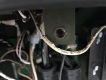
for the member there. And the manual shows where the RED switch is located on the A2 circuit card with white dip switches in it and one can see this thru the clear panels on the A2 and TMs show where and how to set them to resolve the 3665 issue. The same card is used on all models is the reason why this is there. Those see thru plastic covers are a pain to remove and put back correctly to gain access to the A2 but is easier than the side panel to remove.

The manuals are set up at the 8th grade level and were verified three times using regular Soldiers and a group of us civilians checking every step. Painful and they require one to spend a lot of time searching manuals to end up with the solutions with less time on equipment than nose in book. Finding things in the 24 manual is actually time consuming. We used page markers to assist. This is why manuals are so big today. No, after military use and sold at auction was never thought of in the process nor is it in the requirements papers used to devise and design equipment used for a war zone. TMs are not a normal Chilton's manual or SAE shop paper. Everything had to be painfully explained as Soldiers are not extremely well trained to perform tasks needed. If you see yellow sarcastic worded boxes normally with red text in a manual it came from me. They forgot simple to complex in some tasks, example: battery not charging- We say, look at the V belt first as it is easy but the book will have you changing a wire harness or alternator first. Parts are the money makers.

In my training course, I trained soldiers to take it down to the skid, and then put everything together again ensuring each component was operational before being installed including the DCS. Did the same with TQG and Mil Std gens as well. Read thru a task and have what your going to do in mind first, add common sense, and then go to equipment. I would use a cheap laptop on equipment and not your OMEN gaming laptop.

AMMPS are great gens but you really need to have them completely in order first (sometimes hard to do), and only then will they last almost forever under normal operation and servicing. All those bent panels will come off (impact drill helps) and as Guy stated above a hammer and block of wood assists in making them normal again. The rusted bolts issue was never fixed so you will break a few and they put in a nut that is hard to replace on the sheet metal but even an old man like me could use the special tool to put a new on in place. Best to start all the bolts and only then after all are started do the tightening to torque. Don't Baby Huey anything.

You are required to use INPOWER AMMPS or just the INPOWER program and a laptop to gain access to logs saying everything that goes on with your AMMPS and set up some changeable settings. Remember what you are changing and the original setting please or you will be in trouble even to the point of no longer operational. The AMMPS had a USB, but that was changed after the memory stick thing at the JOC in Afghanistan.

Another fault code NOT covered well is a 144 coolant too high. If all components check out, and the code comes constantly back do this. Shut it all off open the main DC breaker. Now set that A2 card dip switch to all off. close the DC breaker and turn on the DCS, and it will say it is not set up or wrong gen setting, and now shut everything off again. Set the A2 Dip switch as it should be and now turn it all on again. Wow, it is all working and you can run the gen again. The 144 won't come back again for a long time. This was found out at Ft. Lee gen school.
 

Attachments

Last edited by a moderator:
Top