• Steel Soldiers now has a few new forums, read more about it at: New Munitions Forums!

  • Microsoft MSN, Live, Hotmail, Outlook email users may not be receiving emails. We are working to resolve this issue. Please add support@steelsoldiers.com to your trusted contacts.

MEP-804A Low Voltage - Voltage Regulator Question

RonK

New member
7
4
3
Location
Vermont
I am troubleshooting a MEP-804A which has what seems to be a common issue: While it is held in START the voltage goes up to 230VAC
but as soon as it is released it drops to about 24VAC.

I have been doing some of the steps that are mentioned in the -24 manual and in various threads here.

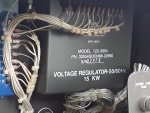
The voltage regulator in this one is a 122-3054 P/N 30554SOCN88-22560

The manual lists 2 options none of which is this one: P/N 01- 21501-1 & P/N 01- 21501-2

I have done the measurement of the disconnected wires from Pins 1 & 3 of the regulator at 34 ohms.
The voltage pot test is 3K CCW and 13.5K CW


If someone can lend some clarity to the VR P/N confusion or suggest some tests that would be very helpful.
Thanks.
 

peapvp

Well-known member
Steel Soldiers Supporter
1,299
1,661
113
Location
Basehor, KS
The Cage number 36024 on the AVR indicates that this unit was made by
LIBBY POWER SYSTEMS, LLC
Doing Business As (DBA)
Division Name
Address35 SARGENT DR
BETHANY, CT 06524 3135
UNITED STATES

check the fuse to the left of AVR first.
 

RonK

New member
7
4
3
Location
Vermont
From the pics posted below it appears to be a Libby. Green paint and Libby showing between the wires.
Which of the two VR test options on the manual should I use?
The P/N on the regulator is none one of the two in the manual.
(P/N 01- 21501-1 & P/N 01- 21501-2)
 

peapvp

Well-known member
Steel Soldiers Supporter
1,299
1,661
113
Location
Basehor, KS
Which of the two VR test options on the manual should I use?
The P/N on the regulator is none one of the two in the manual.
(P/N 01- 21501-1 & P/N 01- 21501-2)
The part number on your AVR deciphers as follows:
30554SOCN88-22560
30554 => Cage Number 30554

Legal Business NameDEPARTMENT OF DEFENSE PROJECT MANAGER-MOBILE ELECTRIC POWER
Doing Business As (DBA)
Division Name
Address5850 DELAFIELD RD BLDG 324
FORT BELVOIR, VA 22060
UNITED STATES

SOCN 88-22560:

Three versions available:
IMG_4681.jpeg
IMG_4682.jpeg
IMG_4683.jpeg

I am not sure, but I don’t think either of the two tests in the manual apply to these three AVR’s

There might be a remote possibility that the test for TRC AVR in manual may work, but could possibly yield different test results
 

RonK

New member
7
4
3
Location
Vermont
The part number on your AVR deciphers as follows:
30554SOCN88-22560
30554 => Cage Number 30554

Legal Business NameDEPARTMENT OF DEFENSE PROJECT MANAGER-MOBILE ELECTRIC POWER
Doing Business As (DBA)
Division Name
Address5850 DELAFIELD RD BLDG 324
FORT BELVOIR, VA 22060
UNITED STATES

SOCN 88-22560:

Three versions available:
View attachment 953863
View attachment 953864
View attachment 953865

I am not sure, but I don’t think either of the two tests in the manual apply to these three AVR’s

There might be a remote possibility that the test for TRC AVR in manual may work, but could possibly yield different test results
Thanks. That is my concern - I would like to avoid potentially expensive mistakes. I wonder if the resistance of the voltage pot might be the clue. 3K CCW and 13.5K CW does substantially agree with one of the options in the manual.
 

peapvp

Well-known member
Steel Soldiers Supporter
1,299
1,661
113
Location
Basehor, KS
Thanks. That is my concern - I would like to avoid potentially expensive mistakes. I wonder if the resistance of the voltage pot might be the clue. 3K CCW and 13.5K CW does substantially agree with one of the options in the manual.
3K to 13.5K matches the 10K potentiometer and 3K resistor listed in the Libby / DoD version 88-22560-1
I would go with this option in the manual and see what you got
 

RonK

New member
7
4
3
Location
Vermont
Per the suggestion to check the transformer, I visually inspected T1. There is no sign of
overheating such as discoloration or melted plastic tape over the windings. Without a
schematic and winding resistances that seems to be the extent of what I can do.


3K to 13.5K matches the 10K potentiometer and 3K resistor listed in the Libby / DoD version 88-22560-1
I would go with this option in the manual and see what you got
Making that assumption I did the tests in section 4-1.1 Testing (AC Voltage Regulator, P/N 01-21501-1, for MEP-804A/MEP-804B).


h. Set multimeter for DC volts and connect positive lead to wire 141A. Connect negative lead of
multimeter to terminal 3 of AC voltage regulator. Start generator set and operate at rated
frequency. Move and hold MASTER SWITCH in START position. Multimeter should indicate
between 4 and 12 VDC.

I measured 10V

j. Set multimeter for AC volts and connect to terminals 10 and 11 of AC voltage regulator. Start
generator set and operate at rated frequency. Move and hold MASTER SWITCH in START
position. Multimeter should indicate 210 to 280 VAC.

I measured 314V

l. Disconnect wire 137A from terminal 5 of AC voltage regulator. Set multimeter for ohms and
connect positive lead to wire 137A and negative lead to terminal 4 of AC voltage regulator. Move
VOLTAGE adjust potentiometer to full counterclockwise (CCW) position. Multimeter should
indicate approximately 3,000 ohms with FREQUENCY SELECT switch in 60 Hz position, and
approximately 0 ohms with FREQUENCY SELECT switch in 50 Hz position. Move VOLTAGE
adjust potentiometer slowly clockwise (CW) while observing multimeter. Multimeter should
increase smoothly to approximately 10,000 ohms.

I measured CCW as 3K 60hz and 0 50hz. CW is 13.5K 60hz and 10K 50hz.

Depending on the tolerance for test section j, that may or may not indicate the regulator is bad.
 

peapvp

Well-known member
Steel Soldiers Supporter
1,299
1,661
113
Location
Basehor, KS
Per the suggestion to check the transformer, I visually inspected T1. There is no sign of
overheating such as discoloration or melted plastic tape over the windings. Without a
schematic and winding resistances that seems to be the extent of what I can do.


Making that assumption I did the tests in section 4-1.1 Testing (AC Voltage Regulator, P/N 01-21501-1, for MEP-804A/MEP-804B).


h. Set multimeter for DC volts and connect positive lead to wire 141A. Connect negative lead of
multimeter to terminal 3 of AC voltage regulator. Start generator set and operate at rated
frequency. Move and hold MASTER SWITCH in START position. Multimeter should indicate
between 4 and 12 VDC.

I measured 10V

j. Set multimeter for AC volts and connect to terminals 10 and 11 of AC voltage regulator. Start
generator set and operate at rated frequency. Move and hold MASTER SWITCH in START
position. Multimeter should indicate 210 to 280 VAC.

I measured 314V

l. Disconnect wire 137A from terminal 5 of AC voltage regulator. Set multimeter for ohms and
connect positive lead to wire 137A and negative lead to terminal 4 of AC voltage regulator. Move
VOLTAGE adjust potentiometer to full counterclockwise (CCW) position. Multimeter should
indicate approximately 3,000 ohms with FREQUENCY SELECT switch in 60 Hz position, and
approximately 0 ohms with FREQUENCY SELECT switch in 50 Hz position. Move VOLTAGE
adjust potentiometer slowly clockwise (CW) while observing multimeter. Multimeter should
increase smoothly to approximately 10,000 ohms.

I measured CCW as 3K 60hz and 0 50hz. CW is 13.5K 60hz and 10K 50hz.

Depending on the tolerance for test section j, that may or may not indicate the regulator is bad.
I am not to familiar with the interpretation of the test results of these AVR’s, there are more knowledgeable members here on steelsoldiers when it comes to these particular AVR’s,

But, looking at the results under J. 314VAC with a max per manual of 280VAC permissible, I would say this might be the problem area to further investigate.
The Potentiometer test is fine
 
Top