• Steel Soldiers now has a few new forums, read more about it at: New Munitions Forums!

  • Microsoft MSN, Live, Hotmail, Outlook email users may not be receiving emails. We are working to resolve this issue. Please add support@steelsoldiers.com to your trusted contacts.


MEP-831a Inverter Overhaul

marcjs14

Member
35
34
18
Location
NC
Hi all - newb here with my first post.

I recently acquired a Fermont MEP-831a from a GovPlanet auction. The unit, with just under 1300 hours, was known to not start, and had numerous fuel leaks. It was also listed as missing some engine parts, although from the auction images the Yanmar L70AE engine appeared complete. I wasn't sure if maybe the inspector was referring to governor/linkage components as part of the "engine assembly".

Having re-plumbed the -4 and -5 (as well as -2 return) lines with correct spec SAE30-10 and/or original Parker hoses, I inspected the rest of the generator, and all appeared intact. I fired her up and she ran, although the governor actuator was notable inactive. I did observe a steady 120V AC displayed on the gauge (frequency counter set to 120V mode). I manually shut her down, and pulled out the governor actuator, at which point I discovered a poor in-field wiring repair which intermittently caused an open-circuit. I quickly mended that with proper soldered joints and Raychem shrink-wrap.

I reinstalled the actuator , adjusted the throttle linkage, and fired her up again. The actuator appeared to hunt quite a bit, and then somethin happened and the AC voltage dropped to 60V AC. I tried to shut off by putting the "run" switch to the stop position. Nothing happened. When I put it back into the run position, the voltage jumped back to 120VAC. However a couple of bands rang out over the moderately noisy engine (backfire-like, but I know diesels don't do that). I thought perhaps a couple of capacitors had blown. Before I could shut her down a mechanical (rubbing-like) sound occurred, and then some smoke poured from the inverter. Sh*t!!!

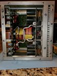
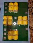
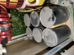
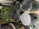
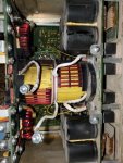
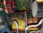
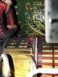
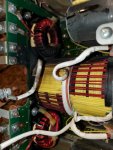
I pulled the inverter and started opening up the enclosure up. So far I can see some discoloration around what appear to be polypropylene capacitors. The logic/control board appears OK as far and no obvious burn marks/etc. It is a seriously-well coated board, no doubt spec'ed for exposure to harsh environments. I plan to take enough apart to get to the power-supply, since I suspect that may contain some electrolytic caps that went "bang".

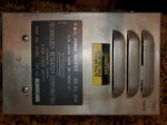
Anyone with experience rebuilding these feel free to chime in. I will post pics once I am able to, and intend to keep this thread updated as I progress. If anyone has a schematic of the inverter (TRC model 29350 - 60Hz), I'd be grateful for a copy!

-Marcel
 
Last edited:

marcjs14

Member
35
34
18
Location
NC
Your title is about a 803A but it sounds like you are working on a 831A.
Dav5, you are absolutely correct - I have no idea how I got myself turned around like that.

Thanks!

I've updated both the title and the thread to reflect reality.
 

marcjs14

Member
35
34
18
Location
NC
I managed to do a bit more breaking-down tonight, and it doesn't appear the cheap-o Panasonic ED's are the culprits as none of the tops have bulged, let alone - burst.

Here are some pics...

It would appear the smoke originated from the large toroidal transformer and perhaps also the smaller one above it in the last three pics. It's past bedtime, so perhaps more tomorrow.
 

Attachments

peapvp

Well-known member
Steel Soldiers Supporter
1,034
1,056
113
Location
Basehor, KS
I managed to do a bit more breaking-down tonight, and it doesn't appear the cheap-o Panasonic ED's are the culprits as none of the tops have bulged, let alone - burst.

Here are some pics...

It would appear the smoke originated from the large toroidal transformer and perhaps also the smaller one above it in the last three pics. It's past bedtime, so perhaps more tomorrow.
The inductors / transformers usually go up in smoke when the capacitors dry out. If the capacitor’s boil over and blow the relief valve, then the thing just doesn’t work any longer, but it saves the iron parts.
the drying out causes an impedance mismatch with the exciter coil.
 

marcjs14

Member
35
34
18
Location
NC
The inductors / transformers usually go up in smoke when the capacitors dry out. If the capacitor’s boil over and blow the relief valve, then the thing just doesn’t work any longer, but it saves the iron parts.
the drying out causes an impedance mismatch with the exciter coil.
Peapvp, thanks for that info. I didn't realize those were inductor coils and not transformers...perhaps good news since they shouldn't be as expensive to replace (so long as available).

What downstream damage might I expect?

I am not impressed with the supplier, TRC, who brag on their website of being "minority owned, women owned..." Who gives a ratts as$ if you can't supply our soldiers with a quality, reliable product???
 
Last edited:

peapvp

Well-known member
Steel Soldiers Supporter
1,034
1,056
113
Location
Basehor, KS
Peapvp, thanks for that info. I didn't realize those were inductor coils and not transformers...perhaps good news since they shouldn't be as expensive to replace (so long as available).

What downstream damage might I expect?

I am not impressed with the supplier, TRC, who brag on their website of being "minority owned, women owned..." Who gives a ratts as$ if you can't supply our soldiers with a quality, reliable product???
There might be a lot more wrong then the inductors. The large caps are probably all dried out as well. You would have to disassemble the entire unit and check all power semi conductors as well.

What is the DC Resistance of your exciter coil?
 

peapvp

Well-known member
Steel Soldiers Supporter
1,034
1,056
113
Location
Basehor, KS
We at INOVA HIGHTECH Ltd. use these Electrolytic Capacitors (MIL-STD):

IMG_4412.JPG IMG_4414.JPG IMG_4411.JPG


The slightly lower cost and smaller footprint version is this here (Industrial Grade):

IMG_4415.JPG IMG_4416.JPG

Nichicon has the highest grade Electrolytic Caps for Industrial Equipment which are by far better but also more expensive then the Panasonic's

IMG_4417.JPG IMG_4418.JPG IMG_4420.JPG
 

marcjs14

Member
35
34
18
Location
NC
We at INOVA HIGHTECH Ltd. use these Electrolytic Capacitors (MIL-STD):
peapvp, so I take it that upping the capacitance from 560uF to 860uF is not an issue?

In most audio (mainly tube) amplifier rebuilds I've performed, more is always better in the power supply, but that is not the case in the signal-path circuitry.

Thanks!
 

peapvp

Well-known member
Steel Soldiers Supporter
1,034
1,056
113
Location
Basehor, KS
peapvp, so I take it that upping the capacitance from 560uF to 860uF is not an issue?

In most audio (mainly tube) amplifier rebuilds I've performed, more is always better in the power supply, but that is not the case in the signal-path circuitry.

Thanks!
That’s correct for Audio DC Power supplies for sure, but here you would have to use the values for capacitance and working voltage from the currently installed caps, but you can choose any cap manufacturer as long as they fit the PCB pattern (lead spacing) and dimensions

i just happened to open one of my several storage drawer’s at random and that drawer had the 860uF in it
 

marcjs14

Member
35
34
18
Location
NC
...here you would have to use the values for capacitance and working voltage from the currently installed caps, but you can choose any cap manufacturer as long as they fit the PCB pattern (lead spacing) and dimensions.
I ordered a dozen NICHICON LGN2G561MELC40...same spec, but improved temperature rating (105 C).
Thx!
 

peapvp

Well-known member
Steel Soldiers Supporter
1,034
1,056
113
Location
Basehor, KS
I ordered a dozen NICHICON LGN2G561MELC40...same spec, but improved temperature rating (105 C).
Thx!
great, they are of a better quality then the Panasonic but also almost twice as expensive.
Glad you found some one who had stock. Mouser shows 0 stock with
200 on order Expected 21-Nov-22
And Digi Key shows 0 stock with 76 week lead time ARO
I suspect that some of the power semi’s and maybe some diodes are toast as well.
Peter
 

marcjs14

Member
35
34
18
Location
NC
Arrow.com had them in stock.

Peter, with the power semi's...is there a way to diagnose them in-circuit, or will that be an ugly desolder/removal/test/replace operation?
 

peapvp

Well-known member
Steel Soldiers Supporter
1,034
1,056
113
Location
Basehor, KS
Arrow.com had them in stock.

Peter, with the power semi's...is there a way to diagnose them in-circuit, or will that be an ugly desolder/removal/test/replace operation?
I am glad you got them from arrow. I also use Future Electronics and Newark.
I buy almost all semis from manufacturer (TI, STM etc) direct because of the cloning and counterfeit’s

as to testing:
in circuits continuity / diode against Ground or 0V plane on PCB and between pins of each semi
Peter
 

marcjs14

Member
35
34
18
Location
NC
This project got shelved for a couple of weeks due to travel...

...my replacement electrolytic caps have now arrived, so I was looking to strip the inverter down to clean, inspect, and swap-out caps.

Anyone know how to best disassemble the unit? Seems a bit of a Chinese puzzle...parts of the enclosure frame unscrew, yet are still joined by hidden welds. Tricky little f'er when it comes to figuring out what to remove to get the heatskin and boards out, as they are wedged in there quite tightly.

A service manual would be ideal, but having inquired to TRC both for a rebuild quote and a service manual got me nowhere.

Thanks!
 

kloppk

Well-known member
Steel Soldiers Supporter
1,977
3,072
113
Location
Pepperell, Massachusetts
Yes, It is a bit confusing on how to get the unit apart to service those capacitors.
I'll shoot some pictures for you on the step by step to get it apart and post them up here.
I've disassembled them numerous times!
 

kloppk

Well-known member
Steel Soldiers Supporter
1,977
3,072
113
Location
Pepperell, Massachusetts
Here is how to get the jig saw puzzle apart :)

This will be two posts since only 10 pictures allowed per post.

Take the top and two large side panels off.
Step 0.jpg

Unplug the three black connectors
Step 1.jpg

Remove the three nuts and bolts attaching the control board to the frame (mine is missing the middle nut and bolt)
As you can see the upper right corner of this board is toast.
Step 2.jpg


Remove the 3 screws at the bottom of the control board
Step 3.jpg

Carefully unplug this short ribbon cable
Step 4.jpg

Wriggle the main control board out just enough to unplug the 2 cables attached to the back of it and then set the control board aside.
Step 5.jpg


Remove the screws attaching the top of the capacitor board to the frame
Step 7.jpg


Remove the remaining screws around the top frame.
Step 8.jpg

Step 9.jpg

Remove the 2 screws on each side of the inverter
Step 10.jpg
 
Last edited:
Top
AdBlock Detected

We get it, advertisements are annoying!

Sure, ad-blocking software does a great job at blocking ads, but it also blocks useful features of our website like our supporting vendors. Their ads help keep Steel Soldiers going. Please consider disabling your ad blockers for the site. Thanks!

I've Disabled AdBlock
No Thanks