• Steel Soldiers now has a few new forums, read more about it at: New Munitions Forums!

  • Microsoft MSN, Live, Hotmail, Outlook email users may not be receiving emails. We are working to resolve this issue. Please add support@steelsoldiers.com to your trusted contacts.

MEP-831a Inverter Overhaul

peapvp

Well-known member
Steel Soldiers Supporter
1,121
1,254
113
Location
Basehor, KS
Peter and Kurt, I am so grateful for your assistance with this project!

I am a mechanical engineer by education, but unafraid of electrical work - which often leads me beyond my knowledge/understanding. Nonetheless, I am happy to learn.

I tested the diodes in-circuit on both sides of the inverter (the burnt and unburnt sides). Using my antiquated Fluke 16 in diode mode, all diodes pass in forward-bias direction with a voltage drop of ~0.4-0.45V. In reverse-bias, the unburnt side voltage drop climbs to ~2.3V before showing the good OL, whereas the burnt plateaus around 1V, and never gives the OL check. Is that an indication that all those diodes are fried, or could the removal of that ceramic disc capacitor be impacting the reverse-bias measurements in some way (as you see I am now clearly out of my lane ;) )
thank you Marcel. Can you tell us the brand name of diodes and power transistor module? Thanks
 

peapvp

Well-known member
Steel Soldiers Supporter
1,121
1,254
113
Location
Basehor, KS
Peter and Kurt, I am so grateful for your assistance with this project!

I am a mechanical engineer by education, but unafraid of electrical work - which often leads me beyond my knowledge/understanding. Nonetheless, I am happy to learn.

I tested the diodes in-circuit on both sides of the inverter (the burnt and unburnt sides). Using my antiquated Fluke 16 in diode mode, all diodes pass in forward-bias direction with a voltage drop of ~0.4-0.45V. In reverse-bias, the unburnt side voltage drop climbs to ~2.3V before showing the good OL, whereas the burnt plateaus around 1V, and never gives the OL check. Is that an indication that all those diodes are fried, or could the removal of that ceramic disc capacitor be impacting the reverse-bias measurements in some way (as you see I am now clearly out of my lane ;) )
Marcel,
Is this now only the diodes (no caps)
Diodes normally fail fully open or short
 

peapvp

Well-known member
Steel Soldiers Supporter
1,121
1,254
113
Location
Basehor, KS
Kurt,

are you going to fix your AVR / inverter too, or you just lollygagging ?

Btw. what brand semis are those? Looks like a BBQ grill….

9F1331CC-EE5F-4009-AF6C-EC9570350E37.jpeg
 

marcjs14

Member
35
34
18
Location
NC
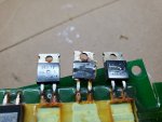
I had to pull a few diodes out of their lake of resin before I could make out the markings...looks like they're good 'ole Japanese IXYS DSEI12-06A FREDs.

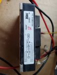
I assume by power transistor module, you are referring to the component in the second image? If so, it too is reliable Japanese (not Chinese junk)...Mitsubishi PRX CM100DU-24H.

Thx
20220820_161705.jpg
20220820_160955.jpg
 

marcjs14

Member
35
34
18
Location
NC
Marcel,
Is this now only the diodes (no caps)
Diodes normally fail fully open or short
Peter, not sure what you meant by your statement above...

...do you mean that the diodes appear to be ok? Why did all diodes on the unburnt side measure OL (eventually) in reverse-bias direction, whereas those on the burnt board (missing the peg-legged ceramic cap) measured 1V in reverse-bias?

Thanks!
 

peapvp

Well-known member
Steel Soldiers Supporter
1,121
1,254
113
Location
Basehor, KS
Marcel,

if they measure 1V in reverse bias that means there is something in parallel to this diode on that board - otherwise it’s infinite or short
 

kloppk

Well-known member
Steel Soldiers Supporter
2,168
3,609
113
Location
Pepperell, Massachusetts
Kurt,

are you going to fix your AVR / inverter too, or you just lollygagging ?

Btw. what brand semis are those? Looks like a BBQ grill….
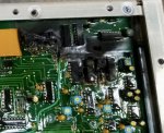
Not fixing it. It's one of several dead inverters I have laying around here. I use it for pictures only.
The charring is from a trace that vaporized. It was the Load signal from the inverter going to the Governor Controller module.
IC's are ON Semiconductor.
 

peapvp

Well-known member
Steel Soldiers Supporter
1,121
1,254
113
Location
Basehor, KS
I had to pull a few diodes out of their lake of resin before I could make out the markings...looks like they're good 'ole Japanese IXYS DSEI12-06A FREDs.

I assume by power transistor module, you are referring to the component in the second image? If so, it too is reliable Japanese (not Chinese junk)...Mitsubishi PRX CM100DU-24H.

Thx
View attachment 876689
View attachment 876690
they could have used IR (International Rectifier) which made their products in the US until 2009 when they where bought by Texas Instruments and shipped all their production equipment to their Chinese facilities together with the equipment from National Semiconductors which they bought in 2010.

The Japanese Corporate boys also discovered the financial joy of manufacturing in China. The parts you got where still made in Japan but wait and see when you get the replacements…..
 

peapvp

Well-known member
Steel Soldiers Supporter
1,121
1,254
113
Location
Basehor, KS
Not fixing it. It's one of several dead inverters I have laying around here. I use it for pictures only.
The charring is from a trace that vaporized. It was the Load signal from the inverter going to the Governor Controller module.
IC's are ON Semiconductor.
At least something American
 

kloppk

Well-known member
Steel Soldiers Supporter
2,168
3,609
113
Location
Pepperell, Massachusetts
I tested the diodes on both of my diode boards with my Fluke. *All diodes measured about .45V and infinity (after the caps charged from my meter)
* Actually I found one of my diodes shorted.
 

peapvp

Well-known member
Steel Soldiers Supporter
1,121
1,254
113
Location
Basehor, KS
Marcel,

I would replace any power semis with IR crossover NOS
AND
Get rid of all off these Yellow Ceramic Disc Capacitors.
It’s basically the yellow death. When they go down they can take quite some circuitry with them…..
 

peapvp

Well-known member
Steel Soldiers Supporter
1,121
1,254
113
Location
Basehor, KS
Peter, not sure what you meant by your statement above...

...do you mean that the diodes appear to be ok? Why did all diodes on the unburnt side measure OL (eventually) in reverse-bias direction, whereas those on the burnt board (missing the peg-legged ceramic cap) measured 1V in reverse-bias?

Thanks!
Marcel,

i usually desolder the device I am testing when I get a reading I am not sure about. This way I know I am testing only that part.
 

marcjs14

Member
35
34
18
Location
NC
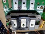
Peter, by power semis are you referring to those 14-pin ICs that are on the control board (BBQ'd on Kurt's board)?

Or are you referring to the power transistor module? BTW, I hadn't paid much attention to it, but when I examined the terminals which shared traces with the failed ceramic cap, it had me wondering whether IT had gone kaput, causing the cap to fry...

20220820_165359.jpg
 

peapvp

Well-known member
Steel Soldiers Supporter
1,121
1,254
113
Location
Basehor, KS
Marcel,
Power semis, like the transistor / igbt module, power diodes etc, basically all the big current stuff
 

peapvp

Well-known member
Steel Soldiers Supporter
1,121
1,254
113
Location
Basehor, KS
Peter, by power semis are you referring to those 14-pin ICs that are on the control board (BBQ'd on Kurt's board)?

Or are you referring to the power transistor module? BTW, I hadn't paid much attention to it, but when I examined the terminals which shared traces with the failed ceramic cap, it had me wondering whether IT had gone kaput, causing the cap to fry...

View attachment 876695
Marcel,

i see what you mean, is the module speak the internal diodes, transistors and igbt’s ok?
I am not sure if those are igbt’s, mosfet or just bipolar
I attached the Datasheet
 

Attachments

peapvp

Well-known member
Steel Soldiers Supporter
1,121
1,254
113
Location
Basehor, KS
Peter, by power semis are you referring to those 14-pin ICs that are on the control board (BBQ'd on Kurt's board)?

Or are you referring to the power transistor module? BTW, I hadn't paid much attention to it, but when I examined the terminals which shared traces with the failed ceramic cap, it had me wondering whether IT had gone kaput, causing the cap to fry...

View attachment 876695
Marcel,

You got two of these Half Bridges with 6 e caps and one of the yellow disk caps on each half bridge? The yellow ceramic cap connects o C1 and E2?
 

peapvp

Well-known member
Steel Soldiers Supporter
1,121
1,254
113
Location
Basehor, KS
Marcel,

to answer your question and if my “wiring diagram “ of this PCB is somewhat close to of what you got, then failing cap would cause some damage to the rectifier diodes. Which, if a diode fails short, would almost certainly cause damage to either or both Half Bridges.

I used the classical inverter design with one dc supply
If this is actually a split supply, meaning you have true positive and a true negative rail with 0V or center being chassis GND and the exciter in between both rails, then damage would be even greater.

i suspect, if I understood Kurt correctly that this is a 3 Phase Rectifier (I drew a single phase rectifier), that this is a single supply rail H bridge design

40313992-BADD-42B5-AB27-6C95FB8C8088.jpeg
 

marcjs14

Member
35
34
18
Location
NC
Peter,

No rush at all - I'm just grateful for yours and Kurt's support. I've gone ahead and ordered a NOS IGBT module just in case. I figure while I'm in here I might as well replace anything which appears suspect (or could be), and hope for the best.

I kind of regret having sourced the slightly shorter (40mm) caps as opposed to the full-height (45mm) version, as the ripple-current is slightly better. Problem was, I didn't find any in stock. Having said that - my MEP-831a saw 1300 or so hours in combat with the USMC before this happened, so I doubt I'll be replacing them again...if so, I'll be an expert!

Thanks again!

-Marcel
 
Top