Made a lot of progress this weekend. I started with 318lbs of 2x4 1/4"wall tubing and welded up a framework bolted to the M105 chassis. Then I mounted the 070A crane (with the 17 ft reach) to the frame. I was going to bolt the crane to the the frame using some grade 8 7/8" all thread. But that would have ended up forcing the crane too far forward to clear the tires. I wanted to get the crane as close to the axle as possible with a little bias to the front. However, mounting the crane straight to the frame would have left too little clearance to the tires. So, I decided to leave the 3" rectangular tubing which had been mounted to the trailer the crane came from, as a spacer to lift the crane up higher. With the extra clearance, I could slide the crane back and still have tire clearance. I welded that tube onto the top of the frame I had made with some 1/8" 7014 rod. The overhead welds were a pain, I can tell I need more practice.
There are some tools you are thankful to have. I used two of them today. The first is my portable bandsaw. The second was a 7" angle grinder with a metal cut-off disc on it. The crane had some extraneous brackets welded on it and the angle grinder made short work of removing them.
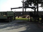
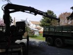
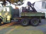
Here are two pictures of the crane after installation. I was finally able to stretch it out to its full reach. Now, the m105 frame is not sufficient to allow the crane to lift its rated capacity of 3000 lbs at this distance, there is simply not enough mass there. However, I am hopeful that it will easily be able to pick up and object beside the deuce and lift it into the deuce bed. My set-up procedure is to use a high-lift jack to raise the frame up slightly to get the outriggers extended on each side. In operation, the weight is supported by the outriggers and front stand.
Pictures coming later this week as I use the crane to load the M105 bed into the deuce. I sold it to a guy who wants to modify it to put on a powerwagon.

 63.1 KB Views: 70
 63.6 KB Views: 70
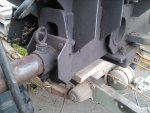 73.7 KB Views: 73
 71 KB Views: 70