• Steel Soldiers now has a few new forums, read more about it at: New Munitions Forums!

  • Microsoft MSN, Live, Hotmail, Outlook email users may not be receiving emails. We are working to resolve this issue. Please add support@steelsoldiers.com to your trusted contacts.

Valence's M116A3 Mounted MEP-803A (10kw generator)

Valence

Well-known member
Steel Soldiers Supporter
2,112
555
113
Location
Davis County, UT
June 20th, 2022:
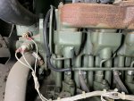
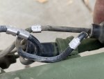
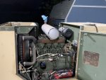
I noticed the tan generator's fuel return line was very deteriorated, but surprisingly wasn't leaking.
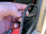
2022-06-19 19.53.12.jpg

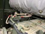
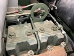
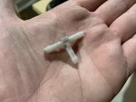
I replaced all the return fuel lines pieces. I had a local place (formerly named "Evco House of Hose" now called "Erik's") match the hose, I think it was 1/8". The supplied hose was a very tight fit on the plastic hose tees and I'm surprised I didn't break any. (I think I didn't at least, I haven't ran the generator much since then).
2022-06-20 20.59.11.jpg 2022-06-20 22.18.09.jpg 2022-06-20 22.17.59.jpg 2022-06-20 22.21.17.jpg 2022-06-20 22.21.31.jpg

Short, pointless, video showing the replaced line:

In the MEP-803A-Onan-Engine-DN4M-TM-9-2815-253-24 technical manual, Figure 5 indicates that this plastic hose tee is #4, P/N 186-6177.
2022-06-20 21.16.15.jpg tm_fuel_injector_and_lines.PNG tm_fuel_injector_and_lines_02.png

In looking to buy a few spares of these plastic hose tees to have as a backup, I saw on eBay that a seller has a brass upgrade version but they don't seem to have very good barbs.
1675284383956.png

Does anyone know of any other good brass replacement tee options?
(I'm just going to tag @Light in the Dark here for good measure, haha)
 
Last edited:

Light in the Dark

Well-known member
Steel Soldiers Supporter
3,860
6,074
113
Location
MA

Light in the Dark

Well-known member
Steel Soldiers Supporter
3,860
6,074
113
Location
MA
The upgrade is a great idea... whomever figured it out originally helped a lot of folks with PM on that poor design. With that said, in my bit of research (part of which was presented above) it could be a better upgrade.

Nothing is cheap these days, investing in unknown demand items in a downward spiraling economy doesn't make it an easier proposition.... but it is something that I have heavily weighed doing. Kind of like the sheet metal parts and the hoses... big upfront money in hopes of making it worthwhile at the end. I would still do it again... I just hope that they still keep moving. Things are very slow there.

The question I have... I wonder if folks who have already done the mod, would unmod to put in a stainless unit? I am not sure they will.
 

Valence

Well-known member
Steel Soldiers Supporter
2,112
555
113
Location
Davis County, UT
I'm actually considering producing the 'ultimate well nut' for folks, but in stainless steel.
The upgrade is a great idea... whomever figured it out originally helped a lot of folks with PM on that poor design. With that said, in my bit of research (part of which was presented above) it could be a better upgrade.

Nothing is cheap these days, investing in unknown demand items in a downward spiraling economy doesn't make it an easier proposition.... but it is something that I have heavily weighed doing. Kind of like the sheet metal parts and the hoses... big upfront money in hopes of making it worthwhile at the end. I would still do it again... I just hope that they still keep moving. Things are very slow there.
I was not aware what you were talking about (about potential, future "well nut" issues on the fuel tank) so I had to do some looking around). For my own future reference, I found this thread, the links in it, and @Triton's PDF write up the most helpful:
https://www.steelsoldiers.com/threads/ultimate-well-nut-repair.171091/post-2070946

The question I have... I wonder if folks who have already done the mod, would unmod to put in a stainless unit? I am not sure they will.
To answer your question, it looks to me that a lot more fittings than just a well nut would need to be replaced to get rid of brass use in the fuel system. I can tell you if I had a well nut that I had replaced and it was NOT leaking, I don't think I'd be looking to replace it. Maybe if you sold a complete conversion kit to get rid of all brass fittings with electroless nickel to newer owners then you might gain some traction but that sounds like a small, hard to reach customer circle(?). However, I'm not the smartest businessman as things that I thought would sell didn't, and other things were a lot more popular.

I would think the biggest issue with the generators is not the potential for slight filter clogging from brass reacting to fuel (and even then that article did seem to be more about biodiesel), but instead the generator not being serviced frequently enough, stagnant/old fuel, and not being ran hard enough for long enough.

Then again, if you marketed towards the off-grid/doomsday people growing their own biodiesel, then maybe that's your ticket?
 

Valence

Well-known member
Steel Soldiers Supporter
2,112
555
113
Location
Davis County, UT
October 28th, 2023:
I replaced the Green 803's trailer plug with a NOS one from eBay. I still need to test the wiring as I discovered that the trailer harness had two lines both identified as "21A". Of course, I only noticed AFTER I unplugged all the old lines from the original trailer harness.

2023-10-28 16.46.06.jpg 2023-10-28 16.56.24.jpg


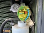
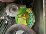
More importantly, today, January 15th, 2024, it had been far too long since I had operated or load tested my generators. Also, since I had not yet changed the coolant in both Tan and Green 803s, I needed to test their freeze point (which I SHOULD have done prior to winter 2022/2023). Each generator was just a little low on coolant by about 1/2 to 1 cup. After running so the coolant would cycle and mostly cool, I tested.

Looks like I had the tester tilted a bit, but I think this was good enough for a sanity check that the Green 803's coolant is at least good -20F, which is more than sufficient for the about +15F lows we're getting right now.
2024-01-15 17.10.55.jpg

The Tan 803's coolant tested better, but I need to be more careful how I hold the tester when inspecting freeze point.
2024-01-15 17.28.16.jpg

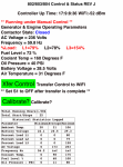
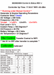
I double checked the internal Reconnection Switch was set to 240V 1PH, and using a pair of 6,000 W, 240v heaters in the garage, the Green 803 chugged very nicely at about 50% load for 20 minutes and I had it up to 75% load for about 10 minutes. It was expelling some little back soot pieces from the exhaust which I assume was left over build up from its previous life being run without enough load. My home current meter reported about 40 amp draw on both legs but then the Over Load fault tripped the connector open. I guess I don't understand how the meter on the front of the generator shows 75% load, but @kloppk 's controller shows L1=79%, L2=78%, L3-154%. Do these refer to the power lug terminals as I don't have anything connected to L2 as it doesn't produce power in the 120/240V, 1PH configuration.

The following is when the Green 803 instrument panel read 75% load:
The first photo is Kloppk's controller, and the second is my home current meter ("Electric Sheep Two" is the "total" current, and actually includes "Electric Sheep One"). This is the configuration that tripped the over-load. To me, the load appears very nicely balanced and I should have still been able to add 12A to each leg for a full 12.5KW load.
2024-01-15 16.29.03.png 2024-01-15 16.30.07.png

The following is when the Green 803 instrument panel read 50% load.
No overload tripping occured here, but again, Klopp's Controller numbers are baffling to me.
2024-01-15 16.29.34.png 2024-01-15 16.30.31.png


Now, actually the most concerning thing to me are the following two things:

1) The Tan 803 shut down immediately after the first start in a long time due to a "Low Oil pressure" fault. The oil was full, ambiet temperature was about 25F. I ran the pre-heater longer and then it started and stayed running without a fault. @Klopp's controller showed 45 PSI while the panel gauge read about 50-ish. I assume that is just a calibration I need to tweek on the Kloppk controller?
2024-01-15 17.19.48.png 2024-01-15 17.09.42.jpg

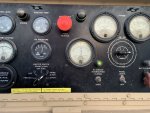
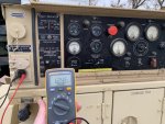
2) And most concerning of all, is that the Tan 803 did not produce power. It did when I last tested it in 2022. When I closed the A/C Circuit Interruptor, my multi meter read 25 or 40V. between L1 or L3 and ground (and the last time I checked it read 0v between L3 and GND). It honestly made me question my sanity. I tripple checked the internal Reconnection Switch and it was still on 120/240V 1PH and the dataplate on the back of the generator DOES say it is an 803 and not some 28v variant lol. Also, as you can see in the photo above, the Kloppk controller reported 47V with infinite frequency, where the front panel reported about 60.5Hz.

2024-01-15 17.18.26.jpg

In better light I shall have to test it again, changing the Reconnection Switch to 120V, 1PH, ensuring the switch is properly seated and not somehow "between" selections. Or maybe it is just a failed part.
 
Last edited:

kloppk

Well-known member
Steel Soldiers Supporter
2,168
3,610
113
Location
Pepperell, Massachusetts
The %Load function on my system is measuring the voltage/current that each winding pair is contributing to the load. It's actually measuring the voltage at the 3 different phase load inputs to K8 the overload relay from the burden resistors.
When in 120 or 120/240 mode the %Load readings from my board should all be about the same value since each winding pair is equally supporting the load.
Yes, you need to perform the calibration function to tweek my system to provide matching accurate readings.
As for the Hz reading the set has to output near proper voltage for the Hz reading to work. Way too low a voltage will cause the inf reading.
The 150 ish % load reading and your contactor opening are likely due to a contact issue in S8. When in 120 or 120/240 contacts 13 and 14 should close which puts burden resistor R13 in parallel with R12. If the resistor paralleling doesn't happen the reading on L3 will be twice the other readings and cause the set to trip an overload. S8 may need cleaning and exercising to correct the issue. Deoxit.
The sets %Load meter only displays the load on one winding pair when in 120 or 120/240.
 
Last edited:

kloppk

Well-known member
Steel Soldiers Supporter
2,168
3,610
113
Location
Pepperell, Massachusetts
Generally the Calibration steps suggest using an accurate external instrument, if available, for reference.
For instance use a DMM to measure the battery voltage at the slave port while calibrating Battery Voltage.
If one doesn't have external references they can go by the sets gauges if they feel they accurate enough.
Oil pressure would require plumbing in an accurate gauge so for most going by the sets gauge is close enough.
 

Light in the Dark

Well-known member
Steel Soldiers Supporter
3,860
6,074
113
Location
MA
On the picture I see no AC voltage on the meter.
Start the set. Check at the 120 volt outlet for 120 volts. What do you get for AC volts?
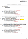
I think this is the magical question here. See the flow chart from the TM (black circle added):
MEP.png

If you didn't build sufficient oil pressure, you will get that light and the machine won't run. If you do build sufficient pressure but the MPU (magnetic pickup) is a little out of adjustment, it could effect the crank disconnect process, and the field may not flash correctly. It very well may be something else, like you could have a flaky field flash relay (see the -24 TM on this machine, page 65 "22. GENERATOR SET FAILS TO GENERATE POWER.") and go through the testing process.

Guys question is one that needs answering first though.
 

Valence

Well-known member
Steel Soldiers Supporter
2,112
555
113
Location
Davis County, UT
On the picture I see no AC voltage on the meter.
Start the set. Check at the 120 volt outlet for 120 volts. What do you get for AC volts?
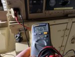
From the convenience outlet I get 26.67 VAC. If I enable the A/C breaker, I get 26.67 VAC between L1 and Neutral and 25.9 VAC between L3 and Neutral (on the terminal lugs)

2024-01-26 18.54.29.jpg


I think this is the magical question here. See the flow chart from the TM (black circle added):
View attachment 914893

If you didn't build sufficient oil pressure, you will get that light and the machine won't run. If you do build sufficient pressure but the MPU (magnetic pickup) is a little out of adjustment, it could effect the crank disconnect process, and the field may not flash correctly. It very well may be something else, like you could have a flaky field flash relay (see the -24 TM on this machine, page 65 "22. GENERATOR SET FAILS TO GENERATE POWER.") and go through the testing process.

Guys question is one that needs answering first though.
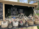
Thank you so much. Beside that procedure to test the A/C interrupter relay (K1), I do need to pull the control box top panel off the rear of the generator as kloppk advised me on the phone last spring (2023) to take the control box top off and check for internal wire chafing and lubricate a switch/connectors (I forget what it was called), which I won't be surprised if that's a related issue. In my defense, the basement flooding last year threw the whole spring/summer into disarray. hah

1706347945213.png 1706348009362.png
 
Last edited:

Valence

Well-known member
Steel Soldiers Supporter
2,112
555
113
Location
Davis County, UT
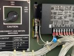
If you only have 26 VDC at the 120 volt outlet, the main generator is not lighting off. What you are reading is exciter voltage. Pull that fat fuse out shown here next to the Volt reg. Test the fuse with your multimeter. Ohms test. You should get continuity.
View attachment 915453
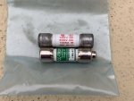
I tested the old fuse (the one with red text, obviously) and it was open circuit, no continuity. I replaced the fuse with an extra fuse I had purchased from kloppk (I wasn’t sure if orientation mattered so I inserted it the same way it was on my green 803).

I now read 124 VAC on the convenience receptacle and (once I close the AC circuit interrupt) 248 VAC across L1 & L3, which is also reflected on the AC Voltmeter panel gauge.
IMG_4968.jpeg IMG_4970.jpeg IMG_4966.jpeg IMG_4967.jpeg

Problem solved! The questions are:

What might have caused this, or what might I have inadvertently done wrong that may have contributed?

And where is a good place to buy more of these fuses to keep on hand?

Thank you again!

Squirrel:
Looks like this generator is due for a wellnut replacement.

IMG_4969.jpeg
 

Guyfang

Moderator
Staff member
Moderator
16,924
24,545
113
Location
Burgkunstadt, Germany
There are a few things that can pop this fuse.
1. A volt regulator going bad.
2. Holding the S1 up for LONG time periods. By that, I mean 1-2 Min. Why would someone do that? Troubleshooting comes to mind.

Dont worry about it. If it happens again, you might talk to Kurt about a new VR.

@kloppk may also be able to shed more light on the subject.

Remember, you sometimes have to hold the S1 up a tad longer, but don't worry about 10-15 seconds.
 
Top
AdBlock Detected

We get it, advertisements are annoying!

Sure, ad-blocking software does a great job at blocking ads, but it also blocks useful features of our website like our supporting vendors. Their ads help keep Steel Soldiers going. Please consider disabling your ad blockers for the site. Thanks!

I've Disabled AdBlock
No Thanks