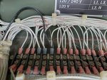
The spring form is the hold down bracket for the electromechanical relays just in front of the TB. One per relay. They tuck into small V notched at each side of the grey plastic base, and slide up and hold the relays down.
Thanks for the info on the spring forms. They were all back behind all the wires and looked like they would cause a short where they were. I assumed that they were part of some wire management system where they were, but your explanation makes perfect sense. I just don't know how the got to where I found them.
If this a set for yourself, if you are in the wrenching mind take the top off and just tackle the return line. Replace it with Viton or some other higher quality return line, and never worry about it again. It can leak anywhere up top, and show up in the back, front, or sides of the machine.
All you need is the right size, small zip ties, and a pack of 1/8" plastic vacuum tees (just as a backup, if they break while doing the job). With the top off the machine, you can also assess the water pump, thermostat, fan belt, fan, radiator, glow plugs, air filter, etc. Its like 30 screws max, and well worth the time as new owner.
I think this is good advice, and I will next weekend if the weather holds.
Dude,
Slow down. First troubleshoot. Then you can start taking things apart. Charg the batterys REAL GOOD. Then we can remove them from the start problem. Read the trouble shooting digram. BOTH of them. There is one in the -10 and the -24 TM's.
Well intended Guy but if I went much slower I would be at a dead stop. I omitted a lot of the trouble shooting steps that I went through, just because it was a long enough post as it was.
Here is the section on engine fails to crank.
1. ENGINE FAILS TO CRANK.
Step 1. Test for defective DEAD CRANK switch, paragraph 2-96.3.
a. If DEAD CRANK switch is not defective, do Step 2.
Dead crank appears to function correctly.
b. If defective, replace DEAD CRANK switch, paragraph 2-96.
Step 2. Check for loose or corroded battery cable terminals or battery posts.
a. If terminals are tight and posts are clean, do Step 3.
Batteries were checked and rechecked connections clean and tight.
b. If not clean and tight, clean and tighten battery cable terminals and posts, paragraph 2-12.4.
Step 3. Check that batteries are installed correctly, paragraph 2-12.5.
a. If batteries are installed correctly, do Step 4.
Batteries were installed in series showing > 25 volts with multi-meter
b. If not property installed, install batteries correctly, paragraph 2-12.5.
Step 4. Test for low or no battery charge, paragraph 2-12.1.
a. If fully charged, do Step 5.
Batteries were freshly charged 12.7 volts each by De Walt charger
b. If not fully charged, replace batteries, paragraph 2-12.
Step 5. Test for defective DC CONTROL POWER circuit breaker, paragraph 2-26.2.
a. If DC CONTROL POWER circuit breaker is not defective, do Step 6.
DC Circuit breaker was initially tripped, no power to panel reset fine
b. If defective, replace DC CONTROL POWER circuit breaker, paragraph 2-26.
Step 6. Test for battery voltage at terminal 1 of starter solenoid. Refer to Electrical Schematic FO-1.
a. If battery voltage is present, do Step 7.
Battery voltage between lower starter bolt and positive terminal on solenoid > 25
b. If battery voltage is not present, check for loose connections from solenoid to batteries.
Step 7. Test for battery voltage at + terminal of starter solenoid with MASTER SWITCH in START position. Refer to Electrical Schematic FO-1.
a. If battery voltage is present, replace starter solenoid. Refer to TM 9-2815-253-24.
b. If battery voltage is not present, do Step 8.
Step 8. Test for battery voltage at input of MASTER SWITCH, refer to Electrical Schematic FO-1.
a. If battery voltage is present at input terminal (6) and ground, do Step 9.
b. If battery voltage is not present, do Step 10.
Step 9. Test MASTER SWITCH for output voltage in START position, refer to Electrical Schematic FO-1.
a. If battery voltage is present at MASTER SWITCH output temninal (7) and ground, do Step 13.
b. If battery voltage is not present at output terminal, test MASTER SWITCH, paragraph 2-47.2.
Step 10. Test for defective battery charging ammeter shunt, paragraph 2-29.2.
a. If not defective, do Step 11.
b. If defective, replace battery charging ammeter shunt, paragraph 2-29.
Step 11. Test for defective Reverse Battery Diode (CR1), paragraph 2-34.2.
a. If not defective, do Step 12.
b. If defective, replace reverse battery diode, paragraph 2-34.
Step 12. Test for defective EMERGENCY STOP switch, paragraph 2-9.2.
a. If not defective, do Step 13.
b. If defective, replace EMERGENCY STOP switch, paragraph 2-49.
Step 13.Test for defective engine fault relay (K12), paragraph 2-33.2.
a. If engine fault relay is not defective, do Step 14.
b. If defective, replace engine fault relay, paragraph 2-33.
Step 14. Test for defective BATTLE SHORT switch (S7), paragraph 2-50.2.
a. If BATTLE SHORT switch is not defective, do Step 15.
b. If defective, replace BATTLE SHORT switch, paragraph 2-50.
Step 15. Test for defective crank disconnect switch (S14), paragraph 2-32.2.
a. If crank disconnect switch is not defective, do Step 16.
b. If defective, replace crank disconnect switch, paragraph 2-32.
Step 16. Test for defective crank disconnect relay (K16), paragraph 2-33.2.
a. If crank disconnect relay is not defective, do Step 17.
b. If defective, replace crank disconnect relay, paragraph 2-33.
Step 17. Check starting circuit for breaks or loose connections, refer to Schematic Diagram FO-1.
a. If starting circuit has no breaks and connections are tight, do Step 18.
b. If defective, repair or replace defective wires or connections.
Step 18. Test for defective cranking relay (K2), paragraph 2-63.3.
a. If cranking relay is not defective, do Step 19.
b. If defective, replace cranking relay, paragraph 2-62.
All of this in yellow is really not applicable to this problem. The dead crank switch, and the Master Switch, and bypassing the switches with a remote starter switch connecting between terminal B on the solenoid and terminal S on the solenoid all behave exactly the same. The engine will start to turn over and then it stops turning and makes a louder clunk, followed by a series of clicks until switching off the Master Switch, the Dead Crank, or Remote Start switch. The Battle Short, the Emergency Stop, none of these things can account for this behavior. They would prevent it from starting, but not from turning over.
If engine were to turn over but not catch I will examine these further. I was concerned the issue is due to a internal mechanical problem which stop the engine or the generator from turning. I then put a socket on the crankshaft and turned the engine over. It never caught, or felt like it hit an obstruction.
Step 19. Test for defective starter solenoid, refer to TM 9-2815-253-24.
a. If starter solenoid is not defective, do Step 20.
The starter solenoid is not defective Switched to TM 9-2815-253-24
EDIT( I am starting to suspect the solenoid may be bad)
b. If defective, replace starter solenoid in accordance with TM 9-2815-253-24.
Step 20. Test for defective starting motor, refer to TM 9-2815-253-24. If defective, replace starting motor in accordance with TM 9-2815-253-24.


