• Steel Soldiers now has a few new forums, read more about it at: New Munitions Forums!

  • Microsoft MSN, Live, Hotmail, Outlook email users may not be receiving emails. We are working to resolve this issue. Please add support@steelsoldiers.com to your trusted contacts.

303M HydraMatic rebuild

rustystud

Well-known member
9,184
2,760
113
Location
Woodinville, Washington
I've been receiving a little interest in the "front servo" upgrade I posted about. I did say it is a drop in installation, but I need to clarify it a bit. You will need to cut off the pipe nut which normally threads into the servo. The later model servos did not use this nut. They just had a straight pipe go into the servo.
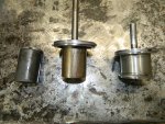
This is a picture of the two pipes.
006.JPG So just cut off the flare end and your Golden !

You will also need to plug this hole with a 1/8" pipe plug. Use a 21/64" drill bit and drill down 1/2" . Then tap out with a 1/8" NPT tap.

001.JPG003.JPGI installed a stainless steel 1/8" plug here.
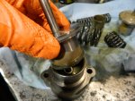
 
Last edited:

rustystud

Well-known member
9,184
2,760
113
Location
Woodinville, Washington
Had a talk with the gasket maker "Gardico" and we're looking at two to three weeks out. Went to the machine shop also. He is extremely backed-up and is looking at maybe three weeks before he can even start on my projects.
I have a few things left to tear down and clean-up. One being the rear oil pump. Actually, I have seven pumps to tear down and clean-up. Also, about seven rear servo's and three front servo's.
I'll post about the rear pump, and anything that pops up during the servo clean-ups.
I still have three more complete civilian HydraMatics to tear down also. I'll post anything interesting.
Other than that, I probably will not be posting much for about a month.
 

rustystud

Well-known member
9,184
2,760
113
Location
Woodinville, Washington
I've been getting ready to visit "plowboy" up in Canada and part of getting ready was rebuilding a Front servo unit for Dave.
I noticed something I never thought to check before. The 303M front servo has a smaller piston then the later (1953 on) civilian HydraMatics . This piston in the civilian models gives you an extra 0.120" larger piston. That's translates into more band holding power. So going to this later style servo not only gives you the "engine braking" ability in third gear, but also gives you better holding power in all the gears with the front band applied.
Also, the 303M piston rod has a hole drilled through it for no reason I can think of. The civilian model has a stronger solid rod.

001.JPG
 

DUUANE

Active member
400
117
43
Location
Qualicum Beach BC
Well you should get some credit as you sold me one of those 303M transmissions. :)
Now If I could only find a few more. Do you have any leads ?
I know where a couple of trucks are.. but seems like they are pretty much the usual runners with no brakes, or no reverse or both. Ill ask Rick at Milspec Hydraulics if he has any spares he can let go.
 

DUUANE

Active member
400
117
43
Location
Qualicum Beach BC
I spoke with Rick this morning. No dice on the cores. He came under the same pressures i did and dumped 90% of his stock. Realestate is so insane here. It makes it almost impossible to run a business out of a rental yard. Constant turnover.
He is always finding more gear. When he gets something he will call me.
 

rustystud

Well-known member
9,184
2,760
113
Location
Woodinville, Washington
I spoke with Rick this morning. No dice on the cores. He came under the same pressures i did and dumped 90% of his stock. Realestate is so insane here. It makes it almost impossible to run a business out of a rental yard. Constant turnover.
He is always finding more gear. When he gets something he will call me.
Well thanks for asking around. I will be visiting "plowboy" in late August. Should see something along the way.
 

rustystud

Well-known member
9,184
2,760
113
Location
Woodinville, Washington
Started cleaning up some valve-bodies today. No special tricks or anything except to watch out for the
"compensator auxiliary plug" . This plug sits behind a pin that must be removed to access the valve. This valve is always stuck ! It is not mentioned in the "TM 9-8025-2" manual. This picture is from another rebuild manual I have. If you can get your valve to move in its bore, then just leave it alone. It is so easy to "cock" this valve and score the bore it's not worth the risk trying to remove it. I also never remove the "exhaust body valve" or the "throttle valve cutoff valve" . Both have plugs that need to be pressed in and usually just get damaged. I just clean these assemblies and make sure the valves move freely.
For the rest of the valves, just be methodical and be sure everything goes back in its proper place.
Above all, "be clean" ! Keep a clean work space.
img009.jpgimg010.jpgimg011.jpg020.JPG
 
Last edited:

rustystud

Well-known member
9,184
2,760
113
Location
Woodinville, Washington
Here's some pictures of a "Sanding plate" I made up using some heavy plywood (1-1/8" ) and some paint sticks and a small pane of glass.
After setting the paint sticks in place around the glass with a 3/4" stapler, I removed the glass and made-up a large quantity of "Epoxy" and applied this to the plywood. Then setting the glass pane back in I carefully pressed the glass into the epoxy. You will need to wipe up any excess that comes out around the glass quickly. Once all the air bubbles are out leave it for a day. You now have an extremely flat surface to wet-sand your valve bodies with. I just use the cleaning solvent from my parts cleaner, and a good quality 400 grit sandpaper.

021.JPG023.JPG013.JPG014.JPG
 

rustystud

Well-known member
9,184
2,760
113
Location
Woodinville, Washington
I'm getting ready to start assembly of the transmission. There are a few things still missing at the machine shop and the gasket manufacturer, but I can assemble the oil pan.
First I needed to check out the integrity of the cooler. I made up a tester awhile back and it works great for this. The "manual" says to pressurize the cooler to 35 to 40 PSI. Well these coolers are now over 50 years old and the cooling system of the engine doesn't go over 14 PSI so I only tested it to 30 PSI which is more than enough.

001.JPG002.JPG003.JPG004.JPG005.JPG006.JPG007.JPG

You can see I put the cooler in a tub of water and then pressurized it to 30 PSI and looked for air leaking out. I tested three coolers today and all worked great.
Later once the cooler is in the oil pan unit I'll pressurize everything checking for leaks.
Water in the transmission from a failed cooler system is the number one failure of the 303M transmission that I know of. Followed by the front pump. So you need to check this system extremely well. You don't want any "strawberry or chocolate shakes" in your oil pan.
 

rustystud

Well-known member
9,184
2,760
113
Location
Woodinville, Washington
So now we're on to the Rear Servo. This little guy can be a real pain to rebuild.
This is one item I would pass on rebuilding if I didn't have the special tool. As long as it passes the air test and the apply rod retracts just leave it alone.
Since I do have the special tool it would be a dick move not to show you how to take this servo apart and put it back together.
Actually it comes apart really fast ! Those springs want to be free ! That is a problem all in itself.
If you have an "Arbor" press you can apply pressure to the spring retainer and remove the two bolts (1/2" wrench) . Now watch out as it will try and get away from you. Once you have it apart. Clean it and check the bores. There are three that need close inspection. I just use a brake hone on all three and clean them up. There almost always scored and slightly out of round. Once all the parts are cleaned and honed then apply your assembly lube and start putting it back together.
Here's some pictures to help you out.
img012.jpg
First we must clean up the bores in the "Accumulator Body" (H) , the main Body (Q) , and the bore in the "Accumulator Piston" . After honing these bores, thoroughly clean them out and dry them.
009 (2).JPG
There are three sealing rings that need replacing or buffing out. To buff the ring's take some "green scotch pads" and really go after those rings. You need a rough surface to help it seal against the cast iron housings.
Check the "Accumulator Body Check Valve" , making sure it is in place and working.

Now the first item to go together is the "booster piston". You will need to be careful as you compress the seal ring. Once it is all the way in it's bore install the inner booster spring and the outer spring. The seal ring on the end of the piston should be "centered" as best you can before installing the "Accumulator Body" . You can twist the accumulator body as you slide it in to help the seal ring go into its bore. Your pressing against those two springs so remember to hold constant pressure against the accumulator body.
Once the body is all the way down and in contact with the Main Body, loosely install one bolt to hold it in place. Make sure one side of the bolt is parallel with the bore to allow the "Accumulator Piston" to be installed. Once the "Accumulator Piston" is in place, install the "compensator spring" and then the "accumulator spring" . Now the real fun begins.
005 (2).JPG
You will need to compress the "compensator piston" into the "accumulator piston bore" at the same time the large "accumulator piston spring" is in place. This is why the special tool is so handy.
001 (2).JPG The compensator piston can easily cock in the bore so you must be very careful here.
012 (2).JPG013 (3).JPG
Once the compensator piston is sliding into it's bore, remove the holding bolt and you can fully compress the springs. Now install the two bolts into the retainer and your done. Pressure test the servo and if you didn't break any seal rings it should retract the apply rod.
img013.jpg
 

Attachments

Last edited:
Top