• Steel Soldiers now has a few new forums, read more about it at: New Munitions Forums!

  • Microsoft MSN, Live, Hotmail, Outlook email users may not be receiving emails. We are working to resolve this issue. Please add support@steelsoldiers.com to your trusted contacts.

CUCV 1986 M1008 - In a Real Pickle - Bad Heads - Need Advice

Commander5993

Active member
Steel Soldiers Supporter
Ok...... does anyone by chance know if there is a belt routing diagram in ANY of the TM's??? :shrugs:
OR if there is one shown here on SS anywhere?
I've been searching for over an hour...

the drivers side alternator is not even close to lining up with any pulley, and I can't figure out which belt is even supposed to run it. aua

----------------
EDIT:
wish I had a second cucv... be nice just to walk over and take a look at things sometimes...
of course if it hadn't been 3 months since i took this apart, i might have been able to remember...:deadhorse:
 
Last edited:

ken

Active member
Steel Soldiers Supporter
2,479
24
38
Location
Houston Texas
Do you have the alt on the correct side of the top bracket? It should be in front of the bracket.
 

cucvrus

Well-known member
11,331
9,874
113
Location
Jonestown Pennsylvania
How about you show some pictures. The Power steering belt goes on first rear groove on crank pulley rear water pump pulley and rear groove on Power steering pump. Then the Gen 1 (drivers side) That goes bottom crank pulley second groove second groove on water pump to front groove Power steering and then up to Gen 1. The Gen 2 goes front crank pulley front water pump and then Gen 2 ( passengers side). Tighten the Power steering one with the Gen 1 belt in place then tighten the Gen 1 belt. Last tighten the Gen 2 belt. Hope that helps. Make sure you have all the brackets attached to the Power steering bracket and they are tight. Good Luck.
 

ken

Active member
Steel Soldiers Supporter
2,479
24
38
Location
Houston Texas
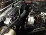
Does this pic help?IMG_0375.jpgThe alt should be in front of the bracket. But the passenger side is behind it's bracket. Also the belts are a different length.
 

Commander5993

Active member
Steel Soldiers Supporter
Does this pic help?View attachment 695577The alt should be in front of the bracket. But the passenger side is behind it's bracket. Also the belts are a different length.
Thanks Ken for the pic. Thats the best angle I've seen yet of the driver's alt.

...... btw... looks like you have a nice lathe there [thumbzup]
one of several tools I really wish I had in my garage... i don't know where I would put it.... but I would make room some how :mrgreen:
 

Commander5993

Active member
Steel Soldiers Supporter
Ok... I'm finally back.
Had some things tie me up for a while, then the power went out... don't know why didn't have a storm or anything, I guess they must just be working on the lines or something.

Anyway, Thanks Guys for the replys on the alternator and belt problems. They helped alot.

With your detailed description Cucvrus, I was able to figure out my belt issue.... So once again Thanks [thumbzup]

I guess I was just tired this evening, the belts were just out of order... when I initially tore everything down, I never actually took the belts off the truck, but rather left them in the water pump/crank pulleys. Apparently the "center" belt somehow hopped over the front belt, and fell onto the fan shaft. When I started to wrap them back around the pulleys this evening, I thought that belt was the front belt and put it into the front pulley groove on the water and crank. Which in turn screwed up the rest...

In any case, after reading your post closely, I went back out to the truck and got that straightened out, and they all look as they should.

Now since I have the belts straightened out, I at least now know which belt the drivers alt is supposed to align with. There might still be an issue with it, as it still seems like it is in between the rear and center pulley grooves, which if true would pull the belt at an angle. However, I have not tightened it up yet. So when I fully tighten the alt bolts down, it may (hopefully) straighten up and align properly. If not, then I may have something bolted up wrong. In any case, I'll look at it tomorrow.

Since thats out of the way, I'm going to post an update on the Intake tonight. I took photos, so it may take me a little bit to get it written and posted.
 

Commander5993

Active member
Steel Soldiers Supporter
Here is my take on:

The "What to do if a company sends you a wrong Head, and you don't have time, money, or patiencesto tear it all back apart and do the job all over again" manual...

The short version, as I know there are many who don't want to read the details:
With the help and input of other SS members, I did get my intake drilled and modified to fit the wrong head. I did have an issue, which was caused by my mistake, but I was able to work around it and fix it. Got it installed and all bolted down, looks like it should work without an issue.


Now, the Long Version:

A little background -
If you didn't see it earlier in this thread, since my original heads were cracked, I ordered a brand new pair off ebay from a company called "odessa*cylinderhead", which had engine heads for almost anything apparently. Upon receiving them, at first they looked good. But later after I had them and everything else was installed, and I went to put on the intake, I found that they had sent me two DIFFERENT heads.

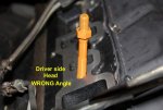
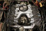
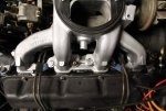
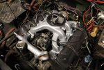
As seen in this photo here, I painted two studs orange so they would show up on camera, showing the two different angles that the intake bolts into each of these heads. They both were supposed to have the angle that the left (passengers side) head has. But they sent me this other one, which ended up on the drivers side.
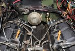
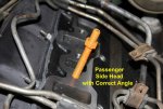
1.jpg 2.jpg 3.jpg


So, my choice was to either
#1
tear everything else back apart and pull the head. Yes this is the 100% right way
#2 modify the intake on one side to fit this different head

Since I am pushing trying to get this truck back on the road, as it is our daily driver, let alone the extra cost pulling the head would incur (head bolts, gaskets, etc). I decided to modify the intake.


So I started with a stock 6.2L Intake Manifold
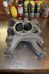
1.jpg


the first thing I did was remove the the two long studs that hold the air filter base on, as I needed to be able to flip the intake onto its top so that I could drill from the bottom side
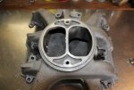
2.jpg


After removing the studs, the first thing that I noticed is the top of the intake is actually angled, and was not a level surface. Since I was going to flip it onto its top in order to drill from the bottom side, I needed the top to be level. Other wise it would cause the holes to be drilled at an angle.
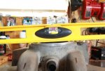
3.jpg


I needed a way to level it, and also I needed a way to clamp it in place so it would move when I drilled each hole.
So I got a piece of ply wood and drilled two holes (plus countersink), corresponding to the threads on the top of the intake where the two studs that removed earlier went.
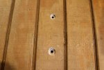
5.jpg


I found a couple of regular bolts in my misc bolt boxes, which had the same metric size and thread pitch (M8 1.25) as the original studs. And would screw into the existing threads in the intake.
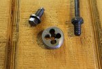
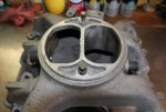
6.jpg 4.jpg


Then I put the screws through the holes in the backside of the plywood, and screwed them into the holes in the intake.
Before tightening, I added a spaced approx 1/4" thick and adjusted it to the proper placement in order to bring the intake top to a level placement.
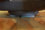
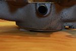
7.jpg 7-2.jpg


I flipped the plywood and intake assembly back over to double check that it was level
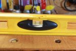
8.jpg


Next, I needed to enlarge my cheap chinese drill press "table", as it was quite small and there was no way it would even hold the intake, let alone the intake bolted to a piece of plywood
So I took a kitchen countertop sink cutout that I had (which I had bought from a local flea market where a cabinet maker sells them for $1) drilled three countersunk holes into it, and used 1/4" bolts to attach it to the drill press.
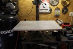
9.jpg


Next I placed the plywood and intake assembly on the drill press, then I added extra wood supports under the center section on the side that I needed to drill, so that it would tilt rock back and forth on the two bolts when drilling, even though I only used light pressure when drilling the holes.
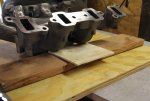
10.jpg


Then I added an another 2x4 and a shim under the end "arm" before drilling. I switched this extra wood support to the opposite end "arm" later.
I used clamps to hold the plywood and keep the assembly from moving.

I tried a 7/16" drill bit first, but when I test fit it, the holes made the bolts a bit to tight to get all of them to thread in properly. So I then re-drilled the holes with a 29/64" drill bit which was one size bigger (as suggested by Barrman in his thread), and test fit the intake on the engine again, and the bolts threaded into their corresponding holes in the head without issue.
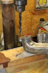
11.jpg


I couldn't drill and hold a camera, so this is what it looked like when I got finished

12.jpg 13.jpg


~ Continued on next Post ~
 
Last edited:

Commander5993

Active member
Steel Soldiers Supporter
~ CUCV 6.2L Intake Modification Continued ~


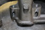
After I finished drilling the intake. I took a sawzall with a metal cutting blade, and cut down the 3 tall original bolt holes, and tried to make them as level as possible for the new bolt angle. Then I took a die grinder with a sand paper disk to clean up the sawzall cuts and smooth everything out.

14 -2.jpg


...then I made my mistake...

After I cleaned up the 3 tall ones that I cut down, I figured I might was well as try to clean up the shorter ones and try to flatten them a bit... completely forgetting that I didn't want to touch the short ones at all, as I was intending on making aluminum wedge washers which would make all the shorter ones level :doh::doh::doh:

As soon as I got done with the die grinder, I realized my mistake... but there was no taking it back at that point. So... how can I fix it now.... I quit for the night and thought about it. Looked at it some more the next morning. And the only way that I could come up with fixing it myself with what I have available to me, was to do some aluminum brazing in order to build up the area around the short bolt holes, so I could make them level.

I want to put up a word of caution here: For those who are not good at brazing aluminum, you probably don't want to try this, and I don't recommend it unless you got a spare intake sitting around. As since aluminum does not change color as it heats up like steel does, it is very easy to overheat the aluminum and very suddenly melt the piece you are working on.
One trick I learned is that if you have a acetylene torch, you can turn on the acetylene only which causes smoke as it doesn't burn fully without oxygen being added, and you can quickly apply a layer of soot to the piece of aluminum you are working on. What that does for you is it gives you a temperature gauge so to speak, as carbon (soot) burns off at approx 900F degrees, which is the temperature where most aluminum brazing rods work at. So when the soots disappears you know that surface temp of the aluminum piece you are heating is approx 900F. BUT aluminum melts at just over 1200F... so you are still not far away... so once you reach this temp, you have to be careful to pull back and just keep the temp high enough to work, but low enough the piece itself doesn't melt. The thinner the piece you are working, the easier it is to melt, as it will heat up faster.


In my case, the Acetylene trick doesn't work... as I don't have an Acetylene torch. Back a couple years ago, I instead opted for a propane/oxy torch set, which I have been very happy with as it is much cheaper to run, propane lasts a long time, and its cuts,
braze, and heats great. But you do need a torch set made for propane, and the correct tips etc.
So since propane burns so clean, even without oxy, it will not lay down a layer of soot on the metal. So the only thing I had to give me some type of temp indication was a "professional" sharpie marker, which the "pro" model ink is supposed to be able withstand heat up to 500 degrees. So I used the marker to cover the area I was going to heat, and when it burned off I knew I was around 500 or so degrees. It wasn't great, but it at least allowed me to see how evenly it was being heated.

Now, I am not good at aluminium brazing... I did actually melt off part of one ear as it was a thin spot, had to let it cool for a few moments, then I had to rebuild it.
Even though it looked ugly, and it took the largest part of the second day just working to modify this intake, I did get all of it done to my satisfaction and save the intake.
After brazing, I did try to see if I could tear any of the brazing off using a set of channel locks, everything seemed to be really solid.
Sorry, couldn't take photos and braze at the same time... and I didn't take any photos right after I got done brazing...


After getting all the brazing done, I once again took the die grinder with a sandpaper disk, and smoothed out my ugly brazing work, and leveled out all the bolt holes.
I then mounted the intake back onto the ply wood board, and ran the drill bit through all the holes again, to clean out the spillover and such some of them had.


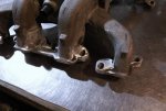
Here it is after clean up


14.jpg


Some of the brazing still looks a bit ugly, almost even like there is cracks in it, but there actually wasn't any


15.jpg


That was the end of day 2 of the Intake mod... but that night I came back and was looking at, and decided to hit it with a coat of "cast aluminium" dupli-color engine paint. Which I had thought about painting it even before I found out about the head issue, since I didn't have a bead blaster or anything similar. It doesn't improve its function any, but it does look a bit better... and a whole lot better than the flakey black paint someone had shot on it before... which I stripped off with "aircraft remover" last week.


16.jpg


The third day, I had to go to the nearest "larger" town (which used up most of that day), and get some longer metric bolts to fit the new height of the modified bolt holes, they didn't' really have the bolts I wanted, so I had to get the closest ones I thought would work, even then they only had 3 so I got 1 longer one, cost almost $12 for 4 bolts. I also got a can of Permatex "The Right Stuff" gasket maker/sealer. Wow... $26 for a 7.5 oz can at o'reillys... (they didn't have the 3oz can)... but it did seem to work well, and was a lot easier to apply than the regular squeeze tube. Plus it should store well.
**As a side note, a few days ago, I threw away a brand new tube of permatex ultra black gasket maker squeeze tube, which had been still sealed in the package until then, the whole tube was completely hard.... I've lost quite a few squeeze tubes which had been opened before, most only used once, but that was the first one that was still sealed and was bad... so yeah the "right stuff" can might be higher... but you should at least be able to use it when you need it, and not loose it.


Anyway, yesterday (forth day), I applied the "right stuff" to both sides of the new fel-pro intake gaskets, sit the intake on, and got it all installed and tightened down. Took some figuring on some of the bolts and studs, as some seemed to short, other were to long. Got it straightened out, added a steel washer for each bolt on the modified side to help distribute the pressure better, and got it all tightened down well.
However, I didn't torque this down as per TM, as I didn't want to take a chance on cracking an ear or something else. I did tighten it down pretty good though, and I kept going around and around rechecking all bolts on both sides, until all the bolts were pretty equal.


17.jpg 18.jpg 19.jpg


So... that is my version of the 6.2L modified Intake to fit the "wrong" type head.

I want to say Thanks again to all the guys who gave input concerning this, and also to Barrman, who modified an intake in similar fashion, and posted it on his thread.
Hope no one else has this problem, but hope this post might be a help to someone to fix something :mrgreen:

Ok.... its late... got to sleep... then back to work on the truck in the morning.
~peace
 
Last edited:

cucvrus

Well-known member
11,331
9,874
113
Location
Jonestown Pennsylvania
laughing-smiley-face-emoticon-7470274734_0a32f112b5laugh.jpggood-report-cardA+.jpgI am impressed with your job. Great JOB. That is what it takes. Many men including myself at times are nothing more then parts replacers. It takes real skill and patience to see thru an issue and improvise and make it work. Anyone can keep throwing money at things in an attempt to make thing work. I would be proud to tell someone I did that job. You worked with what you had and did not sit around and say feel sorry for me. Good Luck. Lets get this truck running again. Another BIG LOSS for the naysayers.
 

ken

Active member
Steel Soldiers Supporter
2,479
24
38
Location
Houston Texas
I have seen that oil fill cap on many CUCV's over the years. Some have the breather style though. GOOD JOB on the intake! Hope it runs as good as it looks. Thanks about the lathe, I also have a mill and other machine tools. They really help when I get myself in a pickle! I like making my own tools. Pullers ,ETC.
 

Commander5993

Active member
Steel Soldiers Supporter
View attachment 695677View attachment 695678I am impressed with your job. Great JOB. That is what it takes. Many men including myself at times are nothing more then parts replacers. It takes real skill and patience to see thru an issue and improvise and make it work. Anyone can keep throwing money at things in an attempt to make thing work. I would be proud to tell someone I did that job. You worked with what you had and did not sit around and say feel sorry for me. Good Luck. Lets get this truck running again. Another BIG LOSS for the naysayers.
ha ha :grin: wow Thanks. I'm satisfied with how it turned out. Wasn't exactly how I intended to do it when I started the modification, but it works and doesn't look like a botched up mess. I like fabricating and building things, its interesting and you never do the exact same job twice. Being able to repair equipment of what ever type, and to figure out how to fix something sometimes, is a skill set that is quickly being lost today.

I'm 34, and I know a lot of people, many older than me who can't hardly change their oil, or replace the blades on their lawn mower. Let alone the current younger generation who can barely tie their shoes... People throw out some equipment for simple problems. I like repairing stuff, and I like to do everything myself whenever possible. For one I don't have the money to pay someone else $50-100 an hour... but also if I do the job, I know how it was done. Now I'm not saying I always know how to fix something or whatever the job may be, but if I can't figure it out then I go to the internet and do some research. I also try to learn to use what ever tools I have available to me to fit what ever is needed.
I have a commercial 4-cycle string trimmer (weedeater) that was given to me, because the repair shop told them it wasn't worth fixing. I tore it down, cleaned and reseated the valves, put on a new carb, and it runs great, and was a big upgrade over the one I had. I also have a 048 Stihl chainsaw (which is around 35 years old) that was given to me because it didn't run, and they had spent over $900 to replace it. I tore it down, put a new set of rings in it, cleaned it all up, put on a new carb, wired in a new switch and mounted it in the rear cover to replace the broken stop switch, and it runs just as strong and cuts just as fast as their brand new $900+ saw, which they've have already had in the shop a couple times now.

I guess I'm like how my Dad is, he worked hard all his life, harder than I've ever had to, but he always said "if a job is worth doing, its worth doing right". And he always did things himself, he's 76 now and doesn't need to be doing a lot especially in the summer because of some health issues. But he still pushes himself, even when I try to do whatever it is he's wanting done. I'm thankful that he instilled in me the... idea I guess, to Learn how to figure out things and make it work. Instead of just taking everything to someone else to have it fixed or throw it away and buy new.

Anyway, thanks again for the comments and all the support through this repair [thumbzup]
 
Last edited:

Commander5993

Active member
Steel Soldiers Supporter
I do have a question. I think you should have a breather cap on the oil fill. Did you put that cap on the truck?
nope, that was the cap that was on it when I bought it. If the guy/shop who had it previously put it on there, I don't know. Didn't know there was a different cap?

----------
EDIT:
After thinking about it, I'm not sure... I can't remember if I replaced that cap or not... it seems like I can remember it was leaking oil out of the cap or something... Could that mean the CDR is bad?
 
Last edited:

Commander5993

Active member
Steel Soldiers Supporter
I have seen that oil fill cap on many CUCV's over the years. Some have the breather style though. GOOD JOB on the intake! Hope it runs as good as it looks. Thanks about the lathe, I also have a mill and other machine tools. They really help when I get myself in a pickle! I like making my own tools. Pullers ,ETC.
Thanks Ken for the comments, and yeah I really hope it runs good without any further issues. If nothing else comes up, and nothing that pulls me away from working on it, I might be able to get it done today. After everything under the hood is done, I just have to finish installing and wiring the temp and oil pressure gauges in the cab... that might be tomorrow.

I like making my own tools too when I can. A lathe and a mill is two tools I would love to get my hands on.
Don't know if I ever will, but people do throw away a lot of stuff these days, maybe someone will throw out those tools too :mrgreen:

Thanks Again [thumbzup]
 
Last edited:

cucvrus

Well-known member
11,331
9,874
113
Location
Jonestown Pennsylvania
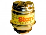
oil cap.jpgYou have my respect. You earned it. I pictured the oil cap that came on the CUCV. Same style that is. It was common on Diesel GM vehicles back in the 70-80's. Still available from Stant. Reference this thread. Thread: CUCV oil filler cap https://www.steelsoldiers.com/showthread.php?15780-CUCV-oil-filler-cap/page2&

I would change it to a breather style. Not worth the chance or argument. May cost $25. but worth the cost and effort. Maybe save a rear main seal. ???? Good Luck.
 

Commander5993

Active member
Steel Soldiers Supporter
View attachment 695687You have my respect. You earned it. I pictured the oil cap that came on the CUCV. Same style that is. It was common on Diesel GM vehicles back in the 70-80's. Still available from Stant. Reference this thread. Thread: CUCV oil filler cap https://www.steelsoldiers.com/showthread.php?15780-CUCV-oil-filler-cap/page2&

I would change it to a breather style. Not worth the chance or argument. May cost $25. but worth the cost and effort. Maybe save a rear main seal. ???? Good Luck.
Wow, Ok. I'll definitely give that thread a read. Like I just editing my previous reply, After thinking about it, I'm not sure... I can't remember if I replaced that cap or not... it seems like I can remember it was leaking oil out of the cap or something... Could that mean the CDR is bad?

I know it didn't have a cap like the photo you posted though.
 

cucvrus

Well-known member
11,331
9,874
113
Location
Jonestown Pennsylvania
If it were me. I know it ain't. I would change the rear main seal if it is leaking. It is nice weather now. If it lets loose in the next few months you will kick yourself in the behind. It takes a while to do. No more then 1 - 8 hour day if you do it right and clean and paint everything but worth it. I like dusty dry engines that don't mark the driveway every where they go. But it is fairly easy and they do have a write up on here how to do it. I never read it but seen it. Just a thought. I would change the cap. It makes sense it was a breather for a reason. CDR was designed with a breather cap. And I can smell the clean oil when it idles because of the breather cap. Have a great day.
 

Commander5993

Active member
Steel Soldiers Supporter
If it were me. I know it ain't. I would change the rear main seal if it is leaking. It is nice weather now. If it lets loose in the next few months you will kick yourself in the behind. It takes a while to do. No more then 1 - 8 hour day if you do it right and clean and paint everything but worth it. I like dusty dry engines that don't mark the driveway every where they go. But it is fairly easy and they do have a write up on here how to do it. I never read it but seen it. Just a thought. I would change the cap. It makes sense it was a breather for a reason. CDR was designed with a breather cap. And I can smell the clean oil when it idles because of the breather cap. Have a great day.
I'll take a look at the main seal, but as far as I know the only leak I did have was from one valve cover, which should be fixed with these new gaskets and sealant. And yes, I would much rather do it now while its still warm weather... as I think its going to be a bad winter this year, all the birds already heading south among other things.

If its supposed to have a vented cap, then I'll replace it. I read the thread you sent, and looked up a cap for a 79 chevy C10 with the 5.7 diesel, as was suggested.

It doesn't look like the same cap you sent in the photo, but is this the "new" style correct one or ??
https://shop.advanceautoparts.com/p/carquest-oil-filler-cap-10078/5020057-P?searchTerm=oil+cap
 
Top