• Steel Soldiers now has a few new forums, read more about it at: New Munitions Forums!

  • Microsoft MSN, Live, Hotmail, Outlook email users may not be receiving emails. We are working to resolve this issue. Please add support@steelsoldiers.com to your trusted contacts.

MEP-004A, No output

peapvp

Well-known member
Steel Soldiers Supporter
1,104
1,214
113
Location
Basehor, KS
Six pack?! Great, I am sure you can handle more than a six pack, I doubt though that your A11 will be able to keep up with you......

I am still wiring A11. This so far it took a 6 pack. Also Houston is flooded big time. Glad I moved out of Houston 40 miles North.

Fuse holder is installed, but if you put it between the J connectors which I did, you will have a hard time torqueing the holder so it will be tight.

When I finish I will show pics.
 

KLChurch

New member
475
2
0
Location
Montgomery/TX
I have one set of wires left to install on the trans.
It has the fuse holder that was installed on the other trans.
Question: If I put a 20 amp fuse in the holder instead on cutting off the holder could I use it as is?
Correction the largest fuse I have is 15 amp.
That would be H2 terminal #2
Kris
 
Last edited:

peapvp

Well-known member
Steel Soldiers Supporter
1,104
1,214
113
Location
Basehor, KS
No, should not be higher then 3 Amps - anything larger and T2 can burn out


I have one set of wires left to install on the trans.
It has the fuse holder that was installed on the other trans.
Question: If I put a 20 amp fuse in the holder instead on cutting off the holder could I use it as is?
Correction the largest fuse I have is 15 amp.
That would be H2 terminal #2
Kris
 

KLChurch

New member
475
2
0
Location
Montgomery/TX
Ok that will be easier. So I will be taking pics tonight after I eat.
After that in the morn I will post the prelim test before I install A11.
Kris
 

peapvp

Well-known member
Steel Soldiers Supporter
1,104
1,214
113
Location
Basehor, KS
OK, enjoy your Dinner! The fuse / fuseholder you had on the 100VA T2 would be fine to use, but I am not sure of Guy [Guyfang] had suggested to you for panel mounting

Ok that will be easier. So I will be taking pics tonight after I eat.
After that in the morn I will post the prelim test before I install A11.
Kris
 

peapvp

Well-known member
Steel Soldiers Supporter
1,104
1,214
113
Location
Basehor, KS
Last edited:

peapvp

Well-known member
Steel Soldiers Supporter
1,104
1,214
113
Location
Basehor, KS
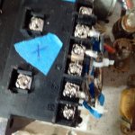
Ok, you got one fuse for each leg, meaning connecting point on the T2 H side - I would take the old fuse for the 100VA transformer out as it defies the logic of having a panel mounted fuse holder - it really doesn’t make any difference if the fuse winds up in the connection to H1 or H2 for that matter as long there is a fuse - I didn’t realize that you had implemented guys panel fuse holder already as in the new wiring diagram for this transformer, so just take out the old fuse holder and splice the two X9 wires to terminal #2 H1 on T2 that will work fine then

No
Now I have one set of wires fused and the other set fused.
The first set was from one diagram and the other from the new diagram.
Kris
 

KLChurch

New member
475
2
0
Location
Montgomery/TX
Ok, let's see Kris

1. Please measure the resistance on Rheostat R2 which is your Voltage Adujst on your Front Panel in your cubicle
This Rheostat has three terminal lugs - two of them are jumpered - please set Voltage adjust to lowest, left setting of dial and measure the resistance with the red test lead on the single connection / terminal and black lead on the jumpered connection / terminals

When done with testing please set dial in middle position

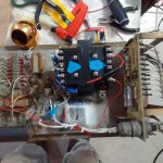
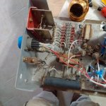
2. Please post some pictures of newly installed T2 in your A11 from some different angles

You may want to have a couple spare fuses, we may have to put 3Amp in like in the situation Brian had

After that we should be ready to go

Thanks Peter
The readings are as follow:
full to left 14.0 ohms
midway 119.0 ohms
full increased 244.0
Kris

Had to wait for the monsoon to stop.
 

peapvp

Well-known member
Steel Soldiers Supporter
1,104
1,214
113
Location
Basehor, KS
Ok,

I guess we are ready! Now, if you have, attach two Alligator Clips to your DMM's test lead - if you don't know of what that is or how they attach than you may not have them or never used them before - On some DMM's they come with the included test leads - not sure what you get with a Klein DMM.....

If you do have them please attach them as indicated and set your DMM to DC - put your A11 into your Genset first without the cover and connect both P/J connectors - then hook up the test leads as indicated in the pic below, as a reminder, both leads have to be connected at the same time as this is 2 pictures combined into one picture - you may have to zoom into the pic to see / read the detail

This way we can monitor T2 during field flash and then excitation while your starting the Genset - this way you wont have to to hold the test leads by hand onto the Test Points.

Hopefully your test leads are long enough so you can put your DMM on top of the Genset above the front panel and monitor everything - maybe you could do a video of it - the entire sequence start with field flash and then going into run with switch to excitation. The switch between field flash to excitation happens automatically when you release the Stop/Run/Start Switch from Start to Run and everything is working.

That would be great! This way we know for sure of what we got!

IMG_20190919_212852.jpg

The readings are as follow:
full to left 14.0 ohms
midway 119.0 ohms
full increased 244.0
Kris

Had to wait for the monsoon to stop.
 

peapvp

Well-known member
Steel Soldiers Supporter
1,104
1,214
113
Location
Basehor, KS
Kris, you can text me the Video, I will upload the video to my YouTube Channel and then post it here as embedded video.

Your Monsoon arrived here yesterday late afternoon in Basehor / Kansas City, Kansas with plenty of windgust's but very little rain moving NNW at a good pace - I guess you fellows in TX got most of the rain


I'm setting up for the start up test but don't know how to insert a video.
Kris
 

KLChurch

New member
475
2
0
Location
Montgomery/TX
Here in texas we keep all the rain (40 inches in 48 hours). Kinda stingy. But I don't think you want to have 4 feet of water in your house. Even though the rain is gone up to you, the streets are still flooded and some of the schools are still closed. Why people move into flood potential areas are beyond me.
I guess they are immortal.

Ok, will video the trial.
What DC voltage should I expect?
 

peapvp

Well-known member
Steel Soldiers Supporter
1,104
1,214
113
Location
Basehor, KS
Great, around 48VDC, like in test #2 for the A11, +/- 5VDC

and when everything is running OK, show your Voltage Gauge on your front panel and use the Voltage adjust Rheostat to see minimum Voltage to maximum Voltage on the Gauge, then move the dial back to 120VAC or 208VAC and see if the Dial of the Rheostat is fairly in the center.
What you see on the gauge depends on where your selector switch is set to: L1-L3, L2-L3, L1-L2, L1-Lo, L2-Lo, L3-Lo

any position between phase and Lo is 120VAC between any two phases 208VAC - this way you can check if your getting voltages on every coil system

dial = knob

Here in texas we keep all the rain (40 inches in 48 hours). Kinda stingy. But I don't think you want to have 4 feet of water in your house. Even though the rain is gone up to you, the streets are still flooded and some of the schools are still closed. Why people move into flood potential areas are beyond me.
I guess they are immortal.

Ok, will video the trial.
What DC voltage should I expect?
 
Last edited:

KLChurch

New member
475
2
0
Location
Montgomery/TX
Good,
I have two settings mV and V
So I will set it at V
Now I just have to find enough guts to do it.
Ill have a friend video it.
But I did not recheck the config board.
Kris
 
Last edited:

peapvp

Well-known member
Steel Soldiers Supporter
1,104
1,214
113
Location
Basehor, KS
and when everything is running OK, show your Voltage Gauge on your front panel and use the Voltage adjust Rheostat to see minimum Voltage to maximum Voltage on the Gauge, then move the dial back to 120VAC or 208VAC and see if the Dial of the Rheostat is fairly in the center.
What you see on the gauge depends on where your selector switch is set to: L1-L3, L2-L3, L1-L2, L1-Lo, L2-Lo, L3-Lo

any position between phase and Lo is 120VAC between any two phases 208VAC - this way you can check if your getting voltages on every coil system

dial = knob

Good,
I have two settings mV and V
So I will set it at V
Kris
 

KLChurch

New member
475
2
0
Location
Montgomery/TX
Great, around 48VDC, like in test #2 for the A11, +/- 5VDC

and when everything is running OK, show your Voltage Gauge on your front panel and use the Voltage adjust Rheostat to see minimum Voltage to maximum Voltage on the Gauge, then move the dial back to 120VAC or 208VAC and see if the Dial of the Rheostat is fairly in the center.
What you see on the gauge depends on where your selector switch is set to: L1-L3, L2-L3, L1-L2, L1-Lo, L2-Lo, L3-Lo

any position between phase and Lo is 120VAC between any two phases 208VAC - this way you can check if your getting voltages on every coil system

dial = knob
So you want me go thru all the settings in the video?
Kris
 
Top
AdBlock Detected

We get it, advertisements are annoying!

Sure, ad-blocking software does a great job at blocking ads, but it also blocks useful features of our website like our supporting vendors. Their ads help keep Steel Soldiers going. Please consider disabling your ad blockers for the site. Thanks!

I've Disabled AdBlock
No Thanks