• Steel Soldiers now has a few new forums, read more about it at: New Munitions Forums!

  • Microsoft MSN, Live, Hotmail, Outlook email users may not be receiving emails. We are working to resolve this issue. Please add support@steelsoldiers.com to your trusted contacts.

MEP-004A, No output

peapvp

Well-known member
Steel Soldiers Supporter
1,134
1,290
113
Location
Basehor, KS
That would be great! This way we got the whole system check, after that you can test your Power output by activating your CKF switch into close position, your CKF indicator should illuminate - leave it in On for a say 30 seconds and then move the CKF Switch in the open position and shut down Genset

We are then ready for the next test to load test your Genset


So you want me go thru all the settings in the video?
Kris
 

KLChurch

New member
475
2
0
Location
Montgomery/TX
Started up the gen.
No volts and no HZ.
Been talking to Peter and we going to make some tests.

The good thing so far is no smoke:smile:
Kris
 
Last edited:

peapvp

Well-known member
Steel Soldiers Supporter
1,134
1,290
113
Location
Basehor, KS
Just a short update:

We had some issues with video taping this - so Kris and his friend are trying to get better videos while we are doing this

On the first test we had no Voltage/Hz indication on Front Panel

Selector Switch is currently set to L1-L2 but during Field Flash Kris got only 100VAC but we should see 208VAC between two Phases

The DMM showed 0V during the entire test indicating that we are not getting any High Voltage at all to the H Side of T2

This we will now further investigate - because both H1 and H2 are wired directly into the reconnection board between T8 L2 and T9 L3

I asked Kris to set Selector Switch to L2-L3 for the next test and to hook up the DMM in AC Volts setting to H Side of T2

This connection goes through P/J13 and I checked J13 when I had the A11 here and it is good. However, I have no clue of what P13 (mating female connector in Genset) looks like or if the wires from P13 to reconnection board are toast from the original T2 failure

We will also check the 120VAC Power to T3 in A11 via Rheostat R2 as one side of the Rheostat connects directly to the reconnection board T9 L3 as well. The other leg of T3 connects directly to the reconnection board T12 Lo

Only other scenario at this point is that the field flash circuit on the currently installed VRBoard is not working right, this is/was not part of the A11 bench tests I performed here, but we need to check for proper High Voltages on the primaries on T1 and T3 first

I will post the next update once we got through the two tests on T2 and T3 and I have proper video to go with it


Started up the gen.
No volts and no HZ.
Been talking to Peter and we going to make some tests.

The good thing so far is no smoke:smile:
Kris
 
Last edited:

peapvp

Well-known member
Steel Soldiers Supporter
1,134
1,290
113
Location
Basehor, KS
Thanks Brian,

If possible, could you do a short video with selector Switch set to L2-L3 (or to whatever Lx-Lx your T2 H1 and H2 is connected to) and Voltage Rheostat in center position and video the Voltage Meter on Front panel from the time before you start moving your stop/run/start switch until the genset is running and has switched from flied flash / excitation? Thanks Peter

Let me know if there is something I can do to help.

Brian
 

Guyfang

Moderator
Staff member
Moderator
17,029
24,882
113
Location
Burgkunstadt, Germany
OK gents, slow down. Lets ask another question first.

Kris, on startup, did you get AC volts on the meter for a very short time? Like as long as you held up the S2 switch? Then when you let go the S2, the AC volts went away? Keep in mind, S9 is responsible for the initial excitation. The A11 can only take over AFTER the initial excitation. Or correct me if I am wrong.
 

peapvp

Well-known member
Steel Soldiers Supporter
1,134
1,290
113
Location
Basehor, KS
Guy,

thats the 100VAC Kris saw during start which I mentioned in post #385 - but the 100VAC are not getting to T2 on H Side - otherwise we would have seen around 20 to 24VDC on his DMM which was hooked up between R and S P/J13


OK gents, slow down. Lets ask another question first.

Kris, on startup, did you get AC volts on the meter for a very short time? Like as long as you held up the S2 switch? Then when you let go the S2, the AC volts went away? Keep in mind, S9 is responsible for the initial excitation. The A11 can only take over AFTER the initial excitation. Or correct me if I am wrong.
 

Guyfang

Moderator
Staff member
Moderator
17,029
24,882
113
Location
Burgkunstadt, Germany
Guy,

thats the 100VAC Kris saw during start which I mentioned in post #385 - but the 100VAC are not getting to T2 on H Side - otherwise we would have seen around 20 to 24VDC on his DMM which was hooked up between R and S P/J13
OK, gotcha. I didn't make the jump from between the L1-L2 and a reading on the meter. Whenever I start one of these things, that's what I want too see first. The AC meter come up. Hertz meter is unimportant. If it moves, its because there is AC voltage present. If not, then the Freq Transducer is bad, or there is no AC volts. And I didn't read if the voltage broke off when S2 was released.
 

peapvp

Well-known member
Steel Soldiers Supporter
1,134
1,290
113
Location
Basehor, KS
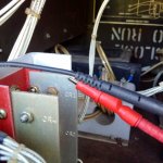
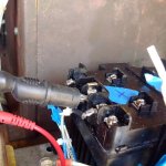
Yesterday Test1:

DMM Plus Lead was attached to: CR1, 2 and 3 Heatsink which is connected to P/J13 S going to F1
DMM Minus Lead was attached to: T2 X2 (which, in our case with new T2 is Terminal #3 and #4 jumpered) which is connected to P/J13 R going to F2

measured per Kris's observation: 0VDC (should have shown a brief DC Voltage during Field Flash)

Connection pics:


IMG_20190921_172055.jpgIMG_20190921_172102.jpg


And first Video in gp3 format with 177x170 resolution and 10 frames per second

https://youtu.be/D-xAgL_BPsQ


Second Video with normal resolution, Kris could not Video while starting the genset - no video of field flash plus he had to trim the video as it was to big for e-mail and he doesn't use dropbox or google drive

https://youtu.be/2Wnn9piNY-I
 
Last edited:

peapvp

Well-known member
Steel Soldiers Supporter
1,134
1,290
113
Location
Basehor, KS
Guy, per Kris, as before 100VAC while S2 in start - but no DC on DMM during that time (we should have seen DC on P/J13 R, S)
makes no sense at this point - to much :beer: could have been a contributing factor yesterday :lol:


OK, gotcha. I didn't make the jump from between the L1-L2 and a reading on the meter. Whenever I start one of these things, that's what I want too see first. The AC meter come up. Hertz meter is unimportant. If it moves, its because there is AC voltage present. If not, then the Freq Transducer is bad, or there is no AC volts. And I didn't read if the voltage broke off when S2 was released.
 

KLChurch

New member
475
2
0
Location
Montgomery/TX
OK gents, slow down. Lets ask another question first.

Kris, on startup, did you get AC volts on the meter for a very short time? Like as long as you held up the S2 switch? Then when you let go the S2, the AC volts went away? Keep in mind, S9 is responsible for the initial excitation. The A11 can only take over AFTER the initial excitation. Or correct me if I am wrong.
Yes when in the start position 100 volts on the control volt meter.
Then in the run, no volts
 
Top
AdBlock Detected

We get it, advertisements are annoying!

Sure, ad-blocking software does a great job at blocking ads, but it also blocks useful features of our website like our supporting vendors. Their ads help keep Steel Soldiers going. Please consider disabling your ad blockers for the site. Thanks!

I've Disabled AdBlock
No Thanks