• Steel Soldiers now has a few new forums, read more about it at: New Munitions Forums!

  • Microsoft MSN, Live, Hotmail, Outlook email users may not be receiving emails. We are working to resolve this issue. Please add support@steelsoldiers.com to your trusted contacts.

mep004 reads 0 phase to phase 480 phase to ground

peapvp

Well-known member
Steel Soldiers Supporter
1,138
1,291
113
Location
Basehor, KS
@peapvp I enjoyed your YouTube video tutorial, which gets to the heart of why paralleling, and load balancing, multiple generators is difficult. Is part 2 somewhere around?

All the best,

2Pbfeet.
@2Pbfeet unfortunately no. I made some changes to my original YouTube channel and accidentally deleted the channel which had featured this video and a few others. All the videos were done in the fall of 2013 and I can’t find the external hard drive I had used to backup the original videos to. I had only this one video on my office PC and found it by luck
 

2Pbfeet

Well-known member
490
919
93
Location
Mt. Hamilton, CA
@2Pbfeet unfortunately no. I made some changes to my original YouTube channel and accidentally deleted the channel which had featured this video and a few others. All the videos were done in the fall of 2013 and I can’t find the external hard drive I had used to backup the original videos to. I had only this one video on my office PC and found it by luck
Darn! That's bad luck.

All the best,

2Pbfeet
 

catienla

Member
52
43
18
Location
anawalt,wv
No output voltage, contactor closed , no gauges other than engine gauges work, test lights won't work. No DC at F1 F2. DC 28v at circuit breaker. Don't think it is exciting fields. Any ideas?
 

Guyfang

Moderator
Staff member
Moderator
17,029
24,888
113
Location
Burgkunstadt, Germany
Are you holding the S1 in the up position long enough?
Have you reset the Fault indicator?
Have you down loaded the TM's from the TM forum, and looked at the troubleshooting diagram?
 

Ray70

Well-known member
Steel Soldiers Supporter
2,658
6,195
113
Location
West greenwich/RI
Can you elaborate on the DC power conditions. Sounds like you have the set running but have no DC power at F1 or F2 but there is power at the DC circuit breaker, and the fault indicator panel isn't working?
I assume you started it normally from S1 ??
 

catienla

Member
52
43
18
Location
anawalt,wv
Are you holding the S1 in the up position long enough?
Have you reset the Fault indicator?
Have you down loaded the TM's from the TM forum, and looked at the troubleshooting diagram?
Can you elaborate on the DC power conditions. Sounds like you have the set running but have no DC power at F1 or F2 but there is power at the DC circuit breaker, and the fault indicator panel isn't working?
I assume you started it normally from S1 ??
Started from S1 held up counted to 10 released and have what I described. Checked for DC at F1 F2 with S1 held up no voltage. DC is working 28v at circuit breaker above F1 F2. Had VR rebuilt and tested by Inova.
 

Guyfang

Moderator
Staff member
Moderator
17,029
24,888
113
Location
Burgkunstadt, Germany
Do you read schematics.


J37 is the the S9 over speed switch C-Plug. The S9-1 contacts are important here. When the S9-1 contacts are in the position shown here, (pins A&B are made contacts) S9 allows the starter to engage, starting the set. At about 800 RPM, (if i remember right) the S9-1 contacts reverse. That means S9-1 pins A&C are made. This is what sends the excitation voltage to F1 & F2 via K5.
1717185038056.png
I would suggest that you first reset the S9 switch with the little button, and give it a try. Sometimes they get stuck. If that will not fix the problem, get the -TM 9-6115-464-34 (Located here in our TM forum if you have not download it yet) and read the test procedure for the S9 switch. If it is the old style S9, do not fool wioth the screw that are safety wired. Factory set. so fool with it at your ownd risk. Do remove the top, and see if all the wires are still hooked to the back side of J37. If its the new style S9, look to see if the wires are still connected to the back of the J37. Not much more you can do with it unless you are an EE.

You wrote:
Started from S1 held up counted to 10 released and have what I described. Checked for DC at F1 F2 with S1 held up no voltage. DC is working 28v at circuit breaker above F1 F2. (has nothing to do with your problem, but still good to know.) Had VR rebuilt and tested by Inova.

Get into the schematics and trace the wires to see if they are good, between P37 and the Special relay box, all the way to the A% card. Look at the A5 card, to see if it has burn spots, traces burnt through and then unscrew the A5 and look at the back side for the same thing. .
 

peapvp

Well-known member
Steel Soldiers Supporter
1,138
1,291
113
Location
Basehor, KS
Did you reconnect F1 and F2 back to the original wiring harness of Genset? You had those two connected to the temporary AVDR054 setup while we rebuilt your A11
Also, have you checked the A5 board as we had instructed you when we shipped the A11 back to you?
 
Last edited:

peapvp

Well-known member
Steel Soldiers Supporter
1,138
1,291
113
Location
Basehor, KS
For the interested reader,
This is @catienla original post of no power from 2022, starting here from post#56 first inspection of A11
The entire repair and testing of his A11 is documented here with pictures beginning from post #56 to end of thread


peapvp

Well-known member
Steel Soldiers Supporter
1,138
1,291
113
Location
Basehor, KS
Just to recap @catienla’s problem and what has been done since his first post in 2022 which is referenced in Post #90 of this thread.

@Guyfang you may want to merge these two posts together as we are dealing here with the original problem

to save everyone time and our collective sanity,
the recap as follows:

1. @catienla posted in 2022 his Genset was running but no excitation when S1 is held in start position

2. during the troubleshooting, @catienla opened up his A11 and posted pictures. Pictures showed visible damage of diodes of AVR board in A11

3. @catienla then decided before fully troubleshooting the no S1 excitation issue to send us the A11 for rebuild and the implementation of using a AVDR 054 as interim solution, which is also documented in a third post unrelated to these two posts of no excitation

4. a further investigation of A5, S9 etc has not taken place as of today.
The A11 was rebuilt in advance, because the A11 in the condition it was in, would have not worked.

so, now we are back at the starting point, to find out where the problem of no excitation is located, but this time with a fully functioning A11
 
Last edited:

peapvp

Well-known member
Steel Soldiers Supporter
1,138
1,291
113
Location
Basehor, KS
Thank you @Guyfang !

For the interested reader who may not be intimately familiar of the excitation and voltage regulator scheme in military generators, a short and simple introduction may be in order at this point.

The 0 hundred series employs a Static Exciter and Voltage Regulator
In our case here, it is simply referred to as A11

Static is defined:
lacking in movement, action, or change,

In our case meaning, passive.
In short, the A11 has no active part in the excitation during the start of the generator.

24V is routed into the A11 on one Canon Receptacle through two pins, which connect internally to the two output wires from the AVR circuit and are connected to two pins of another Canon Receptacle, of which the two exciter coil terminals F1 and F2 are connected to.

The active part of the Excitation circuit is a momentary switch (S1 in start position) , a Relay K5, a contact of the speed switch S9, a power resistor and a Diode on PCB A5

These parts will excite the exciter coil.
Once the exciter coil has been excited and the AVR in the A11 starts sensing a AC output voltage above 30VAC, then the A11 takes over and controls the with rheostat selected output voltage of the generator until the generator is shut down.

if you cannot excite the system, then there will be no power output possible. Regardless if A11 is functioning or not.

If you can excite the system, indicated by app 100 VAC on Voltmeter on Panel and your A11 is NOT working, then you will have output power only as long as S1 is held in start position.

If you hold the S1 for too long in the start position (max 15 seconds), then the Diode and/or power resistor on the A5 circuit board will go up in smoke.

This is the number one cause of no excitation.

sometimes, wires between cubicle, A5 box and A11 are broke, frayed, shortened or have corroded contacts in the canon plugs, the S9 switch is broke or K5 is kaput.

In @catienla’s case here, the decision was made to fix A11 first and fix the excitation issue second.
 
Last edited:

catienla

Member
52
43
18
Location
anawalt,wv
Thank you @Guyfang !

For the interested reader who may not be intimately familiar of the excitation and voltage regulator scheme in military generators, a short and simple introduction may be in order at this point.

The 0 hundred series employs a Static Exciter and Voltage Regulator
In our case here, it is simply referred to as A11

Static is defined:
lacking in movement, action, or change,

In our case meaning, passive.
In short, the A11 has no active part in the excitation during the start of the generator.

24V is routed into the A11 on one Canon Receptacle through two pins, which connect internally to the two output wires from the AVR circuit and are connected to two pins of another Canon Receptacle, of which the two exciter coil terminals F1 and F2 are connected to.

The active part of the Excitation circuit is a momentary switch (S1 in start position) , a Relay K5, a contact of the speed switch S9, a power resistor and a Diode on PCB A4

These parts will excite the exciter coil.
Once the exciter coil has been excited and the AVR in the A11 starts sensing a AC output voltage above 30VAC, then the A11 takes over and controls the with rheostat selected output voltage of the generator until the generator is shut down.

if you cannot excite the system, then there will be no power output possible. Regardless if A11 is functioning or not.

If you can excite the system, indicated by app 100 VAC on Voltmeter on Panel and your A11 is NOT working, then you will have output power only as long as S1 is held in start position.

If you hold the S1 for too long in the start position (max 15 seconds), then the Diode and/or power resistor on the A5 circuit board will go up in smoke.

This is the number one cause of no excitation.

sometimes, wires between cubicle, A5 box and A11 are broke, frayed, shortened or have corroded contacts in the canon plugs, the S9 switch is broke or K5 is kaput.

In @catienla’s case here, the decision was made to fix A11 first and fix the excitation issue second.
Peter, I had high hopes this could be fixed simply, and I wouldn't have to bother you again. Looks like you are involved and Thank You from the start, your knowledge amazes me (and I am sure others). I have some time off from work (broken shoulder) and would like to fix the generator if I can. I will pull manual in the morning and locate A5, S9 and troubleshooting procedure. Thanks again, hope you have been well, Mike
 

catienla

Member
52
43
18
Location
anawalt,wv
Do you read schematics.


J37 is the the S9 over speed switch C-Plug. The S9-1 contacts are important here. When the S9-1 contacts are in the position shown here, (pins A&B are made contacts) S9 allows the starter to engage, starting the set. At about 800 RPM, (if i remember right) the S9-1 contacts reverse. That means S9-1 pins A&C are made. This is what sends the excitation voltage to F1 & F2 via K5.
View attachment 924773
I would suggest that you first reset the S9 switch with the little button, and give it a try. Sometimes they get stuck. If that will not fix the problem, get the -TM 9-6115-464-34 (Located here in our TM forum if you have not download it yet) and read the test procedure for the S9 switch. If it is the old style S9, do not fool wioth the screw that are safety wired. Factory set. so fool with it at your ownd risk. Do remove the top, and see if all the wires are still hooked to the back side of J37. If its the new style S9, look to see if the wires are still connected to the back of the J37. Not much more you can do with it unless you are an EE.

You wrote:
Started from S1 held up counted to 10 released and have what I described. Checked for DC at F1 F2 with S1 held up no voltage. DC is working 28v at circuit breaker above F1 F2. (has nothing to do with your problem, but still good to know.) Had VR rebuilt and tested by Inova.

Get into the schematics and trace the wires to see if they are good, between P37 and the Special relay box, all the way to the A% card. Look at the A5 card, to see if it has burn spots, traces burnt through and then unscrew the A5 and look at the back side for the same thing. .
No formal training on schematics other than school of hard knocks, will start checking in the morning. Thank you guys for info.
 

catienla

Member
52
43
18
Location
anawalt,wv
No formal training on schematics other than school of hard knocks, will start checking in the morning. Thank you guys for info.
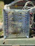
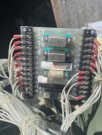
Checked S9 by the TM, it matches the diagram for what is open and closed. Removed A5 and board has 2 traces burnt on the backside. This relay box has been changed it looks new inside as compared to what the A11 did. Took some pics but don't know how to post them to the forum. Where do I go from here?
 

Guyfang

Moderator
Staff member
Moderator
17,029
24,888
113
Location
Burgkunstadt, Germany
Well, you can fix the traces, and try again. Could be all you need to do. Me? I would get in contact with @kloppk . He has a newer and more robust A5 card that he made. There is no telling how old your A5 is, and there may more than just the traces bad. If you fix the traces, follow the test procedures in the -34 TM, to see if all the rest of it works. Its not all that hard of a test procedure. All you need is 24 VDC, 120 VAC and a multimeter. Also test the little silver relays on the board separably. Also easy to test. Just need 24 VDC and a multimeter. Steady hand helps also.
This is not rocket science.
 

peapvp

Well-known member
Steel Soldiers Supporter
1,138
1,291
113
Location
Basehor, KS
Checked S9 by the TM, it matches the diagram for what is open and closed. Removed A5 and board has 2 traces burnt on the backside. This relay box has been changed it looks new inside as compared to what the A11 did. Took some pics but don't know how to post them to the forum. Where do I go from here?
@catienla back in 2022 at your first attempt on installing the ADVR 053 I believe you had at this point, which is documented in this thread, I had asked you the following question


The answer in yet another Thread was, that the unit had stopped exciting after several attempts with the faulty A11 still installed in late 2021 and the S1 switch itself had fallen apart as well.

By the time you posted this thread here above, you had installed the AVDR 053 with a push button, resistor and diode for manual excitation with everything wired into F1 and F2, which was still connected to the A11 and therefor the main wiring harness of the generator

If I remember it correctly, after this failure, you posted the original thread and winded up ordering a AVDR 054 as the 053 was defective. This is my vague recollection of this. Please correct me if I am wrong
 
Last edited:

catienla

Member
52
43
18
Location
anawalt,wv
@catienla back in 2022 at your first attempt on installing the ADVR 053 I believe you had at this point, which is documented in this thread, I had asked you the following question


The answer in yet another Thread was, that the unit had stopped exciting after several attempts with the faulty A11 still installed in late 2021 and the S1 switch itself had fallen apart as well.

By the time you posted this thread here above, you had installed the AVDR 053 with a push button, resistor and diode for manual excitation with everything wired into F1 and F2, which was still connected to the A11 and therefor the main wiring harness of the generator

If I remember it correctly, after this failure, you posted the original thread and winded up ordering a AVDR 054 as the 053 was defective. This is my vague recollection of this. Please correct me if I am wrong
I remember the switch terminal coming off and replacing the switch, my memory of the events that followed the switch were buying the aftermarket AVDR and not being able to get it to work. You contacted me and walked me through the process of building the ugly but functional circuit board on a board to use as a replacement until my original A11 could be rebuilt. I finally got around to installing the rebuilt A11 back on and here I am. I know the A11 was bad and don't know what other damage was done, I need to ask now if you think replacing the A5 is the next step in this repair process or should I repair old A5 and see if everything works. I value your opinion and I hate to keep pestering you guys with my problems, everyone has been very helpful. I took pics of the A5 but don't know how to post them to this forum but will try. The relay box has been replaced, it looks nothing like the A11 did inside, but the traces are burnt on the back of the A5. Many thanks, Mike
 

Attachments

peapvp

Well-known member
Steel Soldiers Supporter
1,138
1,291
113
Location
Basehor, KS
@catienla Mike,

I am posting a few pictures from your zip file.
It looks to me that the burnt traces are connecting to the K5 relay and we should trace their connections and check with the DC wiring diagram to see which part of the circuit they connect to.
There maybe a lot more damage in your Genset then just A5, but we won’t know this for sure until we figure out exactly where these relay points connect to in the overall scheme of things.
I will be back Monday, but someone else may can fill in the voids.

IMG_8188.jpg

IMG_8192.jpg
 
Top
AdBlock Detected

We get it, advertisements are annoying!

Sure, ad-blocking software does a great job at blocking ads, but it also blocks useful features of our website like our supporting vendors. Their ads help keep Steel Soldiers going. Please consider disabling your ad blockers for the site. Thanks!

I've Disabled AdBlock
No Thanks