• Steel Soldiers now has a few new forums, read more about it at: New Munitions Forums!

  • Microsoft MSN, Live, Hotmail, Outlook email users may not be receiving emails. We are working to resolve this issue. Please add support@steelsoldiers.com to your trusted contacts.

mep004 reads 0 phase to phase 480 phase to ground

peapvp

Well-known member
Steel Soldiers Supporter
1,104
1,214
113
Location
Basehor, KS
When the A11 failed how many times and for how long did you push the S1 switch from run to start?
The generator will always produce a excitation when S1 is moved from run to start while running and you will see a voltage of 80 to 100 on panel voltage meter while S1 is in Start
And meter is set to L1 / L2
 

peapvp

Well-known member
Steel Soldiers Supporter
1,104
1,214
113
Location
Basehor, KS
Update:
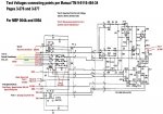
Mike performed the following test and we measured the following A/C voltages and Genset running:

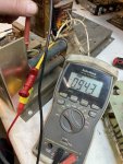
L1 + L3 = 0.8VAC
F1 to F2 1.8vac

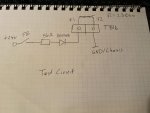
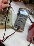
Voltage across F1/F2 is app. 0.9 VDC with a current limiting resistor of 56 Ohm

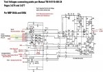
8BF97477-F6B4-49BE-B3FF-C4970B90730C.jpeg
 
Last edited:

peapvp

Well-known member
Steel Soldiers Supporter
1,104
1,214
113
Location
Basehor, KS
the head diodes usually conduct around 0.4V so the 0.9V on F1/F2 with 56 Ohm resistor is high enough to have them open up and create a magnetic field inside the Genset rotor

so we should be seeing some much higher AC voltage on L1/L2/L3
 

jamawieb

Well-known member
1,437
556
113
Location
Ripley/TN
It should be showing some kind of voltage with those readings. The rotating diodes inside the head are known to fail. Easy access below the gauge cluster. Have to take the panel off the back of the head to gain access
 

catienla

Member
52
43
18
Location
anawalt,wv
It should be showing some kind of voltage with those readings. The rotating diodes inside the head are known to fail. Easy access below the gauge cluster. Have to take the panel off the back of the head to gain access
Anyone know a part no. for the diodes? I would like to have them here before I tear it apart. Thanks, Mike
 

peapvp

Well-known member
Steel Soldiers Supporter
1,104
1,214
113
Location
Basehor, KS
Mike just repeated the above test, but this time he pushed the Pushbutton while measuring L1/L3 and we got:

Peter, So glad you posted the last message. I didn't know to measure while button was pushed. Went out and checked it again, it shows 60-80 vac holding 1-3 seconds.
 

peapvp

Well-known member
Steel Soldiers Supporter
1,104
1,214
113
Location
Basehor, KS
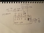
The sequence then will be:

connect meter to L1 / L2 in AC Range

1. Start Generator
2. Set governor control to 60 Hz
3. Activate CB1 (Crkt BRK Close)
4. Push Pushbutton
5. Watch AC Meter
6. Once voltage is over 60VAC release Pushbutton
7. Adjust new 1K Ohm Potentiometer for desired Genset output voltage

then check voltage between each L to N and between all L’s
 

peapvp

Well-known member
Steel Soldiers Supporter
1,104
1,214
113
Location
Basehor, KS
Mike and I will continue this thread tomorrow evening and we will update everyone and explain the phenomenon of residual magnetism and it’s impact on the ADVR 054 and why this system needs a Pushbutton lockout feature.

so folks, stay tuned
 

peapvp

Well-known member
Steel Soldiers Supporter
1,104
1,214
113
Location
Basehor, KS
The Oshkosh folks sold their ADVR 053 / 054 with a EB500 Auto Exciter to prevent accidental flashing of an already flashed system because of the self excitation feature of the 054 and the issues they had with the Pushbutton excitation on the 053 system

the 053 was discontinued by manufacturer and the Oshkosh folks are out of the 054 / EB500 kits at the moment

Mike and I will update you on a lockout version which utilizes only the 054 with Pushbutton or S1 switch

stay tuned…..
 

Attachments

peapvp

Well-known member
Steel Soldiers Supporter
1,104
1,214
113
Location
Basehor, KS
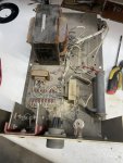
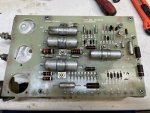
Mike sent me his A11

Here is a first look and update:

03443A64-0C92-4A3A-BFA5-7404F2AFCC68.jpeg

AVR is taking his first bath in decades;

98047F49-AA41-48A5-ABA7-D0FD3399E476.jpeg

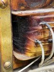
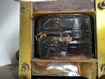
T2 is still ohming out ok on primary and secondary, but I don’t think he will survive a Highpot test…..
3067E624-D6AE-4493-B9BF-116BC29C7D5C.jpeg
321ACD7B-0192-4844-8611-01BD4467E27C.jpeg
0AE52361-3E4B-492A-AB3C-DAC7D25E08BE.jpeg

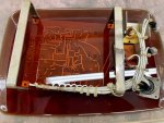
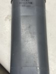
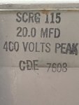
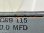
C2 on the other hand is in great shape and the best one I have seen so far.
Date of Manufacture: Week 8, 1976

E5BD7EA0-112A-420C-801C-FF88618D4073.jpeg
870E4C69-267E-44FD-AC08-C9F0BBDB397E.jpeg

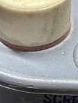
The top seals are still intact and you can see the colors red and black

7E0869D4-678B-4E11-9896-BD5A1EADE694.jpeg
D7EBE609-2CF8-4CA8-8B33-8781008ABA13.jpeg

But the deterioration has started:

F75BD975-7754-460E-B9BC-2EE78FE92BEC.jpeg
 

peapvp

Well-known member
Steel Soldiers Supporter
1,104
1,214
113
Location
Basehor, KS
Curious as to what the cap tested at.
20.12uF with the ESR below 100 mili Ohm

A new capacitor would have about 10 mili Ohm ESR in this size, type and rating.

Eventhough the Cap is still in excellent shape, it is causing the T2 transformer to get warm to hot

Secondary is a 120V center tap X2 connected to/ with Exciter Coil F2 and GND.
This cap sits across both legs X1, X3 and serves as Power Factor Correction.

This is also the first A11 I have seen which did not have C3 and C4 installed which are EMI Suppression Capacitors

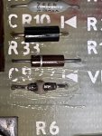
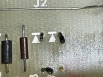
The AVR has blown Diodes CR7, CR8 and CR21
That’s why it is taking a bath until tomorrow morning.

I will post updates here as we progress

Peter

50B7B649-02E3-4331-8D1B-D26661421B96.jpeg

C120E512-6FB0-45E1-A15D-74EB6AC5EDFB.jpeg
 

peapvp

Well-known member
Steel Soldiers Supporter
1,104
1,214
113
Location
Basehor, KS
Update:
We got the board stripped. Took 20 hours soaking in stripper due to age and thickness.

Conclusion:
The Diode CR22 failed first due to old age. This failure disabled the voltage sensing capability of the AVR. So the AVR increased output Voltage to exciter coil to maximum which then in turn caused a to high of a voltage coming back into T2 which supplies the power. The Voltage here is normally 208VAC but in this case it may have gone up as high as 270VAC on L1 + L3. This then killed Diodes CR7 and CR8 and one of the SCR's
both SCR's should be replaced as well as the old glass Diodes CR12 to CR21 (the entire row)
The pictures below are repair and TEST 1
We apply 95VAC to T3 and measure 22VDC across R15. That means the entire Voltage sensing circuit is OK now.

When I replace the two SCR's we can proceed with Test 2 (Power test) and then Test 3

Peter
DC3B4CBE-90DE-49A8-9884-AE7ACB01C7FA.jpeg
35BBA9CF-C91E-4844-AEB6-346BAC868EE1.jpeg
492A51B2-D8F0-4A71-9B5B-3FE665561C9F.jpeg
52172414-7E08-46B5-A8F9-D74F5D752ED4.jpeg
476F75AD-4608-4374-AF33-EB8C69EF364F.jpeg
10490611-1A22-4753-87BB-DB3380FB7738.jpeg
 
Last edited:

Guyfang

Moderator
Staff member
Moderator
16,689
23,875
113
Location
Burgkunstadt, Germany
Typical A11 failure. It happened so often in the 90's, that the A1 became an automatic return upon failure. You simply turned it in, and got a new one. No one, at least here in Germany, repaired them anymore.
 
Top