• Steel Soldiers now has a few new forums, read more about it at: New Munitions Forums!

  • Microsoft MSN, Live, Hotmail, Outlook email users may not be receiving emails. We are working to resolve this issue. Please add support@steelsoldiers.com to your trusted contacts.

My M813 gets a turbo!

US6x4

Well-known member
Steel Soldiers Supporter
1,234
2,246
113
Location
Wenatchee, WA
In an effort to compensate for the power loss of running 16.00-20s (still a future mod), I started accumulating parts for adding a turbo to my NHC-250. The direction I'm going is nothing new as @Lonnie has already laid the ground work for the turbo layout I'm using, but I was also inspired by sbkarmen and Sevin7 who also mounted theirs backward. Lonnie's routing solved some issues and checked some boxes for my install that lets me retain the factory intake and its cold starting features, does not interfere with where my heater ducting will enter the firewall by the PCB and doesn't require that I spend a month on an english wheel to make a cross over tube to fit between the hood and jake brakes.

Before attempting a turbo add-on I wanted to have several things in place so now that I have a pyro and boost gauge to keep an eye on the vitals, the jake brakes installed which would affect pressure pipe routing, and my heater location figured out, I'm finally ready to put the turbo on!

20200529_171759.jpg

20200417_184345.jpg

20180920_173309.jpg


Typically my projects are completed before I do a write-up on them but this one is still underway so follow along and I'll update as I make progress. I'm a detail guy so I'll have plenty of photos of the parts, the steps involved, and the cool parts I got to produce to make this all work out!

All of my favorite car shows were cancelled back in May and June so I started the teardown in early May.
20210506_124627.jpg

The muffler bolts wouldn't budge even after 3 days of soaking in Kroil and other things so after snapping off a reducer with the impact wrench I just yarded out everything in one piece. The manifold bolts came right out with just a few tight squeaks :)
20210506_131204.jpg

20210506_131216.jpg


Shipments of part$ started rolling in such as the new-style pulse manifold, the Borg Warner BHT3B turbo, the silicone elbows and aluminum pipes, 5" exhaust parts, and some hose fittings.
20210329_160638.jpg
20210329_162906.jpg
20210407_103233.jpg
20210407_100619.jpg
 
Last edited:

US6x4

Well-known member
Steel Soldiers Supporter
1,234
2,246
113
Location
Wenatchee, WA
20210410_143707.jpg
This is the basic aluminum pressure pipe routing before I cut any pipes to length. Starting at the lower left and going clockwise there is a 3.5" 90° elbow, a 3.5" straight pipe, a 3.5" 90° elbow, a 3.5" 45° mandrel bent pipe, a 3.5" to 4" reducer 90° elbow, a 4" straight pipe, and lastly a 4" to 5" 90° elbow going into the intake. I tried to reduce the amount of connections both on the pressure piping and the exhaust piping and I think it will turn out just fine.

20210506_135532.jpg
20210506_135947.jpg
20210516_083936.jpg20210516_131129.jpg
The silicone boots and aluminum pipes I got from siliconeintakes.com and I had to choose between 1 ft. or 2 ft. lengths. All of the 1 ft. lengths were available with a rolled bead but the 2 ft. pieces were not. Turns out I needed lengths in between 1 & 2 feet.

20210516_132349.jpg
20210516_132334.jpg

I cut about 4.5" off of each side of the 45° pipe going over the bell housing.
20210516_143916.jpg
20210517_155955.jpg
20210517_155850.jpg
My copper compressor tube ended up being right in the way of the 4" pipe.
 

US6x4

Well-known member
Steel Soldiers Supporter
1,234
2,246
113
Location
Wenatchee, WA
With the pressure pipes fitted and cut to length it's time to roll some beads! A friend from work happened to have a bead roller that he had never used and broke it out just for my pipes!

20210519_160410.jpg
20210521_161140.jpg
20210523_113429.jpg

By the third pipe we finally got the hang of how to steer the pipe and locate the bead while we rolled them.
20210523_113444.jpg
20210603_151823.jpg

The 45° tube is not symmetrical: the passenger side is 8" to the center of the curve on the OD and the driver side is 7 3/4" to the same spot. If I run a tape down the back of the bend the overall length is about 16.5". The straight 3.5" tube is 14.25" long and the 4" tube is 19.5" long.

Next up is some of the exhaust piping!
 

US6x4

Well-known member
Steel Soldiers Supporter
1,234
2,246
113
Location
Wenatchee, WA
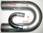
After much searching I was finally able to find the perfect 5" 180° mandrel u-bend pipe off of a seller on ebay (automods_llc) to come off of the turbo outlet.
I wasn't sure if I would have to hack-n-whack to make it work but I figured this was the tightest I could find and I would have the mandrels bends there to use piece-meal if necessary. Turned out to be a near perfect fit!
s-l400 (4).jpg
20210506_155017.jpg
Here is the turbo adaptor flange with its 22° Cummins flare and the u-bend ready to get chopped!


20210506_162017.jpg
20210510_091532.jpg

I ground off the aluminized layer so the TIG welders at work would have an easier time with it. The cut for these two pieces was close. Right at the tangent for the u-bend and for the adapter piece I cut it just a 1/2" past the start of the reduction. The TIG welder did say he had some challenges with it mainly because I didn't remove a wide enough path of aluminized coating. For the other downstream bends I made sure to remedy that.
20210510_091546.jpg
20210513_091042.jpg
20210513_091025.jpg
20210516_083444.jpg
20210516_083508.jpg
20210516_083527.jpg
 

US6x4

Well-known member
Steel Soldiers Supporter
1,234
2,246
113
Location
Wenatchee, WA
Next in line is the muffler which needed to be mounted as far forward as I could get and still leave the muffler clamps a straight piece of pipe to seal against. I ended up nibbling off about 5/8" off of each end of the muffler to get it to fit how I wanted. This included first extending the slot by 5/8".

20210522_130144.jpg
20210526_173251.jpg
20210526_174404.jpg
Drill a hole to retain a radius at the end of the lengthened slot.

20210527_091151.jpg
Running the muffler through the band saw made the worst screeching sound I have ever heard (and I grew up with very annoying sisters...)


20210528_161611.jpg
20210528_161619.jpg
The muffler was perfectly content dangling from the u-bend pipe and my brother came over to help with the fitting and cutting of the series of 90° mandrel bends from the muffler to the stack.

20210528_161626.jpg
The pipe coming out of the muffler is a un-cut 12" x 12" pipe, the following is another 12" x 12" pipe with one straight side cut off at the tangent line, and the final bend is a 18" x 18" with one end at the almost tangent (I'll measure later) and the other end trimmed by 1" to remove some rough pipe where the stack will go.

20210528_161630.jpg
20210529_163559.jpg
There was a full day of on, off, on again, adjusting, measuring, finessing, and since the tack welds never held what I ended up with was a bunch of permanent marker orientation lines for the TIG welders to align and glue together. Let's get those pipes welded!
 
Last edited:

US6x4

Well-known member
Steel Soldiers Supporter
1,234
2,246
113
Location
Wenatchee, WA
One of the TIG welders at work had these cool pipe stands that just made the setup super simple and dead nuts on. I'd never seen them in use before. This time I ground off more aluminization and it turned out better.

20210629_182552.jpg
20210607_115151.jpg
20210607_115209.jpg
20210607_115202.jpg

Now this curve can be clamped on to the muffler so that all the pipes can be swung into position so that the stack elbow is centered in the fender hole and then I can take measurements for some brackets.

20210609_182107.jpg
20210609_182028.jpg
20210609_182508.jpg
20210609_191938.jpg
I removed the factory saddle brackets from the block and relocated one of the brackets forward to the next set of holes so that I can design and build a bracket that mounts the muffler to the block just like the original setup. Next up is some CAD work (cardboard-aided design) !

20210612_172152.jpg
20210612_172203.jpg
That 6" mark would be the center of the muffler but to re-use the saddle clamp to engine block attaching strap I moved the saddle mount brackets to the 4" mark. There's still a possibility that the oil return line will interfere with that factory strap.
 
Last edited:

US6x4

Well-known member
Steel Soldiers Supporter
1,234
2,246
113
Location
Wenatchee, WA
With the cardboard version looking close enough I got the parts laser cut out of 1/4" steel, then I deburred and polished the edges and had it bent up at work. I was able to talk a friend into MIG welding the pieces together and it turned out sick!

20210622_131957.jpg
20210622_091641.jpg

Below are the only pics I have of making the lower saddle clamp. Starting with 3 1/2" wide by 3/16" thick flat bar I learned to use the rollers to curve the metal and then cut out the area you see in black cross-hatch. Then the tabs get bent down with a special jig in the 30 ton press since u-shaped parts cannot fit in the CNC press brake.
20210615_090553.jpg
20210621_100706.jpg

Verify fitment before welding.
20210618_195234.jpg
20210623_091432.jpg
20210623_091611.jpg

Then back up and let the welder have at it!
20210629_182419.jpg
20210623_153311.jpg
20210623_153322.jpg

The top saddle clamp is half-way finished at the moment and since Covid has messed up the supply of P&O steel, all of these parts were cut on hot rolled so I'm still going to sand blast and tumble the parts before they get painted.
 
Last edited:

US6x4

Well-known member
Steel Soldiers Supporter
1,234
2,246
113
Location
Wenatchee, WA
To support the weight of the stack with all of its leverage on the pipes and the pipes downstream of the muffler I decided to tie into the large fender support structure. With the muffler moving along with the engine vibrations and rocking and with the fender support being stationary I built in 4 vibration isolators to give parts a chance to move somewhat independently. First up is the 3D model, then the cardboard, then the real deal.

PIPE SUPPORT ASSY.JPG
PIPE SUPPORT ASSY 2.JPG
20210613_144951.jpg
20210613_144957.jpg
20210617_164135.jpg
20210617_164151.jpg
20210617_164608.jpg
20210617_164623.jpg
20210617_194832.jpg
20210617_194824.jpg
 
Last edited:

US6x4

Well-known member
Steel Soldiers Supporter
1,234
2,246
113
Location
Wenatchee, WA
This must be some sort of hardened steel because my brand new drill bits had a hard time getting through it.
20210617_201117.jpg
20210617_201909.jpg
20210617_201926.jpg
20210617_201957.jpg

Making these brackets out of 1/4" seems kinda overkill right now, but that's how the rest of the truck is anyways. I think 3/16" would have been perfect. These parts are also waiting to get blasted and tumbled before paint and whether or not the 4 isolators restrict motion too much is yet to be determined. I may have to remove 2 of them.

This is where the perfect size of the u-bend comes in. With the combination of the upside down manifold, upside down turbo and the u-bend together, the pipe leaving the muffler and heading toward the hole in the fender only runs down hill by 1° - It's almost completely horizontal. it's all on a direct path to the stack with only 1° of compensation for the downward angle of the motor itself. The support sits at 40° so the pipe support bracket got bent at 41° to catch the pipe.
20210529_165707.jpg

20210529_165837.jpg

I still have lots of reservoir tank work to do to relocate that to the firewall and all of the parts will need to get painted. This is as far as I got up to now so stay tuned for updates!
 
Last edited:

Mullaney

Well-known member
Steel Soldiers Supporter
Supporting Vendor
7,716
19,766
113
Location
Charlotte NC
This must be some sort of hardened steel because my brand new drill bits had a hard time getting through it.
View attachment 838455
View attachment 838456
View attachment 838457
View attachment 838459

Making these brackets out of 1/4" seems kinda overkill right now, but that's how the rest of the truck is anyways. I think 3/16" would have been perfect. These parts are also waiting to get blasted and tumbled before paint and whether or not the 4 isolator restrict motion too much is yet to be determined. I may have to remove 2 of them.

This is where the perfect size of the u-bend comes in. With the combination of the upside down manifold, upside down turbo and the u-bend together, the pipe leaving the muffler and heading toward the hole in the fender only runs down hill by 1° - It's almost completely horizontal. it's all on a direct path to the stack with only 1° of compensation for the downward angle of the motor itself. The support sits at 40° so the pipe support bracket got bent at 41° to catch the pipe.
View attachment 838468

View attachment 838469

I still have lots of reservoir tank work to do to relocate that to the firewall and all of the parts will need to get painted. This is as far as I got up to now so stay tuned for updates!
.
Wow. That is about all that can be said.
You are a heck of a fabricator!
 

US6x4

Well-known member
Steel Soldiers Supporter
1,234
2,246
113
Location
Wenatchee, WA
I drilled the exhaust port for the pyrometer probe and mine is a little too long as I suspected so I added a 1/4" NPT female to male adapter to take up some space.

20210506_135319.jpg

20210608_091356.jpg

20210608_091406.jpg

20210608_091728.jpg

20210608_112248.jpg
This is a special "interrupted thread" tap where the teeth on each flute cut a different thread. It makes tapping cast iron a breeze because I've had some taps in the past that just got mangled trying to apply enough downward force to get the threads to bite into the cast iron. This just grabs and goes.

20210608_112341.jpg

20210608_164647.jpg
I tapped the rear 3 cylinders common exhaust port because the word on the street is that these run hotter than the front so the pyro should be reading the worst case temperatures.
 

Mullaney

Well-known member
Steel Soldiers Supporter
Supporting Vendor
7,716
19,766
113
Location
Charlotte NC
I drilled the exhaust port for the pyrometer probe and mine is a little too long as I suspected so I added a 1/4" NPT female to male adapter to take up some space.

View attachment 838503

View attachment 838504

View attachment 838505

View attachment 838507

View attachment 838506
This is a special "interrupted thread" tap where the teeth on each flute cut a different thread. It makes tapping cast iron a breeze because I've had some taps in the past that just got mangled trying to apply enough downward force to get the threads to bite into the cast iron. This just grabs and goes.

View attachment 838508

View attachment 838509
I tapped the rear 3 cylinders common exhaust port because the word on the street is that these run hotter than the front so the pyro should be reading the worst case temperatures.
.
Nicely done. I can't speak for the temperature differences.
All I know it that on a Gas 6, everything towards the back runs hotter too.
 

US6x4

Well-known member
Steel Soldiers Supporter
1,234
2,246
113
Location
Wenatchee, WA
Looking good... your exhaust & inlet piping looks a lot like mine.

I'm still working on fitting my 3rd Jake brake that I copied from you lol...
Thanks Lonnie. Yes, I'm following your lead on this type of pipe routing. It looks so simple, but there are dozens of steps involved...
 

US6x4

Well-known member
Steel Soldiers Supporter
1,234
2,246
113
Location
Wenatchee, WA
Today I'm disassembling all the exhaust components so I can degrease them and rough them up with maroon scotchbright pads before painting them with OD Green high-temp machine gun suppressor paint. While it’s apart I took some more measurements as promised.

20210705_090659.jpg

The 180° u-bend got whittled down quite a ways with the top leg cut being 9" from the outside of the bend and the bottom leg being just 13" from the same point. The muffler is a 9" OD x 10" long body DYN87Q-500-145 Dynaflex brand part.
20210705_093143.jpg

20210705_093341.jpg

20210705_093806.jpg
18" x 18" elbow got cut at around 8 3/4" from the outside of the pipe.
 
Last edited:

WillWagner

The Person You Were Warned About As A Child
Super Moderator
Steel Soldiers Supporter
8,539
2,758
113
Location
Monrovia, Ca.
Both of you guys have done an amazing job! You might want to think about putting some flex between the hard engine mounted components and the body/cab mounts. 12 inches is the minimum needed. If no flex is used, things like to crack, usually flange of the pipe to turbo, but the muffler and everything to the engine are one. The outlet of the muffler will be the weak point. Won't happen in a day, just something to ponder.
 

US6x4

Well-known member
Steel Soldiers Supporter
1,234
2,246
113
Location
Wenatchee, WA
With this configuration and with the limited amount of space available to use on these 5-tons you definitely end up prioritizing form over function. For awhile I was contemplating a straight pipe exhaust where a flex pipe or true bellows would have easily fit in place of my muffler, but now the only straight section I have is the part perpendicular to the frame after the muffler at 8" long. I agree that the muffler exit will be the weak link and luckily that joint is not welded; having that compression clamp right there may buy me some time.

Seeing the rub marks on my mirror frame tubes from the stack is evidence of how much these engines move - and that's scary! It will be interesting to see how my vibration isolators handle that amount of movement...
 
Top