• Steel Soldiers now has a few new forums, read more about it at: New Munitions Forums!

  • Microsoft MSN, Live, Hotmail, Outlook email users may not be receiving emails. We are working to resolve this issue. Please add support@steelsoldiers.com to your trusted contacts.

.

74M35A2

Well-known member
4,145
334
83
Location
Livonia, MI
Mostly doing engine stuff right now. Clutch inspection cover plate and release bearing grease tube arrived and test fit OK.

Clutch Housing Cover.jpg

Leaving trans PTO cover plate off until trans installed. Don't think I will be able to use the side mount 6 bolt window, we'll see.
 
Last edited:

74M35A2

Well-known member
4,145
334
83
Location
Livonia, MI
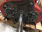
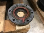
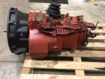
Pulled the input shaft collar today on lunch to reseal it. No seal present or oil action behind it as mentioned, so back together it goes with a new gasket. Looks like the only front leakage could be the countershaft front bearings, but there will be a new gasket from clutch housing to trans body anyway, so she will hopefully stay dry for a while.

Trans.jpgTrans2.jpg
 
Last edited:

74M35A2

Well-known member
4,145
334
83
Location
Livonia, MI
Trial fit of clutch cover with hydraulic air-assisted release fork, flywheel, inspection cover, and pilot bearing. Not knowing where to set depth of pilot bearing, I simply set it flush with the flywheel hub surface (not crank side). Three foot 2"x4" and a few hammer whacks put that bad dog in its place. Depth measures OK comparing to trans input shaft pilot journal length. Will check again tomorrow, I measured it at 3am, and got 2 different numbers. Need to be back at work by 8'ish.

T1.jpgT2.jpgT3.jpg
 
Last edited:

OpieNoTool

Member
158
4
18
Location
Boyne City MI
I just stumbled on to this thread. I have a m929a1 that we use daily in our excavtion buisness. We swapt trans last year to a 9-5 13 speed. It was time consuming project but results were well worth it. I can tell u a few problems we had. Transfercase lever and linkage were in the way and had to be removed. Which was problamatic and never used. We had a 2 inch spacer machined to make up the drive shaft length being longer. Between trans and transfer case. Clutch linkage is from an 800 series which we modified. The pto however being a dump truck was the worst part. We had to use 45 degree adapter and notch the bottom of the frame rail slightly as the engine sits tight to the passenger side. Adding the 45 adapter also spins the pto oppiste of stock so we went with a double acting pto. Floor cross members had to be cut and refabricated to clear shift tower. We used a different style intermediate shaft with round flanges as fuller did not make that wing style yoke for the 13 speed. Best of luck to ya. If i get time when i get home from vacation i will try to get a few pics for u non believers
 

74M35A2

Well-known member
4,145
334
83
Location
Livonia, MI
Thanks. I assume you did not use the engine flywheel housing that was originally installed with the Allison auto? That housing appears to have 1" additional depth for the torque converter, vs a standard flywheel housing (not trans side clutch housing). Also, when you say intermediate shaft, do you mean the driveshaft from the trans to transfer case? I think you are saying that you had this shaft made up with a different U joint yoke one each end? Makes sense if so.

Here is a nice short Eaton reference on which output yoke styles are available for the transmission and their part numbers (half circle, full circle, or flange), I have yet to measure the U-joint on my 925a2 at the back of the Allison, but pretty short I will also need to extend this shaft about 2" as you said. 1" for shorter trans, and 1" for shallower engine flywheel housing.

http://www.roadranger.com/ecm/groups/public/@pub/@eaton/@roadranger/documents/content/ct_042146.pdf


Thanks for your input. I'm going hydraulic clutch and considering to use the bottom 8 bolt PTO flange on the trans instead of the right side 6 bolt one, but we'll see how far it hangs down. I traded some stuff for an 8 bolt pump (6 bolt on an 8 bolt adapter plate). Will note rotation as you mentioned. May also do engine mounted clutched pump instead, as it gives more control choices, easy to turn on/off while driving, can raise the bed as you are approaching overpasses, etc.....
 
Last edited:

OpieNoTool

Member
158
4
18
Location
Boyne City MI
Mine has a 250 cummins and we did use the original bellhousing. There was a spacer on the end of the crank that had to be removed and a spacer put on the starter to shim out correctly. Yes im refering to the drive shaft between the transmission and transfer case. We had a drive shaft out of an oshkosh that had the round flange same as the axels. Yes they make a wing style yoke for a fuller but its larger. Weller truck parts is who we buy all are semi parts from and they couldnt find anything close. I swapped the input yoke on x-case tothe same as both out put shafts. The large pto on the bottom is directly over the front drive shaft.
 

simp5782

Feo, Fuerte y Formal
Supporting Vendor
12,131
9,415
113
Location
Mason, TN
Mine has a 250 cummins and we did use the original bellhousing. There was a spacer on the end of the crank that had to be removed and a spacer put on the starter to shim out correctly. Yes im refering to the drive shaft between the transmission and transfer case. We had a drive shaft out of an oshkosh that had the round flange same as the axels. Yes they make a wing style yoke for a fuller but its larger. Weller truck parts is who we buy all are semi parts from and they couldnt find anything close. I swapped the input yoke on x-case tothe same as both out put shafts. The large pto on the bottom is directly over the front drive shaft.
Its called a companion flange

Sent from my SM-G935P using Tapatalk
 

74M35A2

Well-known member
4,145
334
83
Location
Livonia, MI
Mine has a 250 cummins and we did use the original bellhousing. There was a spacer on the end of the crank that had to be removed and a spacer put on the starter to shim out correctly. Yes im refering to the drive shaft between the transmission and transfer case. We had a drive shaft out of an oshkosh that had the round flange same as the axels. Yes they make a wing style yoke for a fuller but its larger. Weller truck parts is who we buy all are semi parts from and they couldnt find anything close. I swapped the input yoke on x-case tothe same as both out put shafts. The large pto on the bottom is directly over the front drive shaft.
Interesting, thanks. Because you used the longer flywheel housing, I wonder if your trans input shaft is in the clutch and flywheel pilot bearing by 1" less. From measuring the "standard" flywheel housing depth I bought, the 5" depth housing is required to avoid this. If I used the 1" deeper flywheel housing, the clutch discs will still be on the trans input shafts, but the tip of the trans input shaft would not be supported by the pilot bearing anymore, it will be 1" rearward, hanging in space. 250 engine should be the same situation, and removing any flywheel spacer would make it even worse.

Thanks for your input, I'm not picking a fight, just trying to figure out if I can use my stock flywheel housing, but from depth and shaft measurements, it does not look like it would work. Well, it would work, but not for long, as the trans input shaft would not reach the pilot bearing.

Creative work on the transfer case input flange swap.

Any pics would be fabulous. Thanks.
 
Last edited:

OpieNoTool

Member
158
4
18
Location
Boyne City MI
Good luck with your build. If i have time i will post some pics. As for your flywheel deal not sure what to tell you. My bell housing is the same thickness as the 350 cummins bellhousing we pulled the flywheel out of. Sounds like u have done your reserch like i said good luck
 

Jbulach

Well-known member
Steel Soldiers Supporter
2,672
2,220
113
Location
Sunman Indiana
Hmmm... possible A2 is different depth for different torque converter I keep hearing about? Always assumed it was just internal, stall speed difference?
 

74M35A2

Well-known member
4,145
334
83
Location
Livonia, MI
Not sure. I don't know anything about the 250 flywheel housing depth. I do know on an 8.3 that the M939a2 housing for the Allison MT654CR is about 6" deep. On the ISL (auto trans, Allison 6 speed), and the commercial 8.3L with the factory 6 speed manual I acquired, both of those flywheel housings were 5" deep. Plus it was confirmed through drawings the 939a2 8.3L housing is an additional 1" deep (post #136 this thread). So, I assumed the 5" depth one is "standard" and I am using it for test fits. So far, the deep dish flywheel and trans input shaft all seem to measure up correctly, based on how far in the flywheel pilot bearing is vs the length of the trans input shaft. I have not mated them together yet. If I can find a way to easily actuated the hydraulic clutch throw out while the engine and trans are on the pallet at idle, it would really help to confirm I have everything right. I do have a mechanical clutch housing also for it, I could try and just put a pry bar on the lever to actuate the clutch.

I'll ask Simp to measure the stock 250 flywheel housing depth for the 250 folks who are following this and want to pursue it. He should have a removed one from changing his truck to the Cat trans he put in.
 
Last edited:

74M35A2

Well-known member
4,145
334
83
Location
Livonia, MI
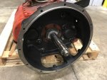
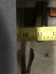
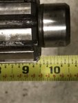
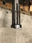
Pilot bearing face to trans face measures 9-3/4" with the 5" deep flywheel housing. Trans face to pilot bearing journal on trans input shaft measures same, 9-3/4". Should be good. If I use my stock mil flywheel housing which is 1" deeper, the trans input shaft will not be supported, as the pilot bearing is only 1/2" wide.

IMG_4418.jpg IMG_4419.jpg IMG_4420.jpg
 
Last edited:

74M35A2

Well-known member
4,145
334
83
Location
Livonia, MI
Rear main oil seal and oil pan resealed, so I was able to install the flywheel for good, and the clutch. Flywheel is a cup or pot type, and had 6 drive pins which locate to a floating drive plate between the double-disc clutch. I then installed the clutch housing upside sown so I could get a clear view and feeling of how the release for engages the throwout bearing. Will remove and install it on trans correct way next. I was surprised at the precision fit of the Eaton pressure plate cover. No need to really move it around, there are flanges that fit within the flywheel to locate it. I held the alignment tool up slightly when tightening the cover down, experience has been if you just let it hang down with weight on it, things will not line up well. Alignment tool easily goes in and out, we should be good to stab a trans on the back of it. Recommended Viton sealed pilot bearing installed into flywheel. ISL engine is SAE rated at 400hp / 1200ft-lb of torque, this double disc ceramic clutch is rated for a max of 1400ft-lb of torque. Cup / pot type flywheels are not common anymore, but this was the only way of holding that torque level in a SAE #2 setup, which means using a 14" flywheel, as SAE #1 is typically a 15.5" flat face flywheel. I could have changed to an SAE #1 flywheel housing, but chose to simply reuse the housing that came with the RV engine I purchased, as the mount pads look reasonably close to the mil Allison housing. Trans input shaft is 10 spline, 2" diameter.
 

Attachments

Last edited:

74M35A2

Well-known member
4,145
334
83
Location
Livonia, MI
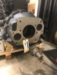
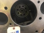
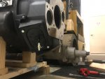
SAE #2 clutch housing is now installed onto the 13 speed trans. This is a hydraulic release housing only, no provision for mechanical linkage. Second port is only inspection window. New gasket with hi-tack on it, and cranked down with a 1/2" impact. Forklift was out of battery otherwise I would have done a test fit onto the back of the engine. I have to change out 2 bolts as the length changed from one housing to another. I also have to get 4 shorter clutch pressure plate bolts. Small Allen drive locking screws went in to secure the flywheel plate drive pins, so now the bolts which occupy those holes are too long.

IMG_4564.jpgIMG_4565.jpg
 
Last edited:
Top
AdBlock Detected

We get it, advertisements are annoying!

Sure, ad-blocking software does a great job at blocking ads, but it also blocks useful features of our website like our supporting vendors. Their ads help keep Steel Soldiers going. Please consider disabling your ad blockers for the site. Thanks!

I've Disabled AdBlock
No Thanks