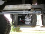
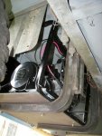
RE: Re: enclosing the genset
After speaking with Gillette, and trying several tests, I have learned alot about the unit.
1. it should run at 61.5Hz no load
2. no-load volts might only be 113/226VAC or so.
3. half-load volts should be about 125/250VAC
4. full load volts should be about 115/230VAC
This is because the set's alternator is compounded, meaning that the more current is drawn, the higher the voltage goes, until at about half-load, the set's internal resistance starts to affect the ability to pass enough current to maintain the voltage, so that at full load, the voltage is back down to the lower limit of the spec. At a tested 1250 watts resistive load, the voltage was 115/230V. -so the unit needs some load.
In obeisance of the factory's advice, with a resistive load, I will next measure the voltage and frequency at increments up to 6KW output in order to be sure the generator (alternator) is in order.
The load will be made of electric stove elements which are about 1KW each at 240VAC. I will make this load bank and note the voltage/power curve as well as the frequency. (At this point because of their kind and thoughtful explanations, I am begining to suspect it is OK, and what I have is an unpleasant mix of reactive and bizzarre electronic loads -I have not even addressed the air conditioners' power factors, but later for that.)
When everything in the shelter is on, I get 108VAC. When I turn -off- the four "dual 40 watt high efficiency electronic ballasts", the voltage rises to 113V. I may have a very nasty electrical load. Not only some power factor issues but some capacitor-input rectifier loads. Such loads cause high peak currents right at the crest of the voltage waveform and cause harmonics.
Info:
"Emergency engine-generator sets, installed to provide power during utility outages, usually aren't very large. Thus, they're very limited in their capacity to handle harmonic loads and may fail during an emergency."
Well mine won't fail because it is oversized, but it is obvious that the load is probably the issue. Below are two simulations representing a combination of the four 64-watt electronic ballasts, and a normal resistive load. (please disregard any apparent discrepancies, as the software was degined for actual power DC supplies and therfore has to be tricked with regard to an AC load)
red = load current
green = AC line current
blue = AC line voltage
yellow = load voltage
Both powered loads "R1" are, at the end of the day, resistive. The value of R1 was adjusted between the simulations to bring the resistive load power to be about equal.
The load's power in the resistive circuit is:
72.8V * 11.37A = 827W
The load's power in the reactive circuit is:
157.8V * 5.26A = 830 watts
(the differences in the RMS voltage and currents shown are due to one being a simple rectifier and one having a large DC filter capacitor that keeps the voltage higher by charging all at once at the peak of the half-cycle of AC voltage waveform, and then maintaining the voltage by slowly discharging during the rest of the AC voltage half-cycle.)
Notice the high peak AC line currents in the one with the reactive load, as well as the accompanying distortion of the AC line voltage waveform resulting from these abrupt changes in current.
The load on the generator is already at 13A, and the reactive load of the flourescent ballasts adds 35-amp spikes to this. The generator is rated for 25 amps. The spikes are too short in duration to blow the breaker, but they cause huge power losses because during the time of the spike, the load due to the spike is 35A*120V or 4200 watts. It's just like a power surge, repeating over and over...
The spikes occur near the peak of the AC waveform. Not only that, but a harmonic energy of 5 times the 60Hz AC frequency is being generated. The 4200 watt pulses of harmonic energy, repeating 120 times a second, is what damages electrical equipment. This cannot be stopped by surge supressors. Those things supress voltage surges only.
Now, see the simulation of a resistive load. This is representative of of regular light bulbs. Notice how the voltage and current curves are nicely aligned, and there are no sharp pulses or distortions in the waveforms. In fact, the voltage and current start and stop at the same time. How nice. How desirable.
(NOTE: although the current (IR1) shows a 17 amp peak value, the RMS value of this 11.37A as calculated. I showed a >2* higher average current load for the resistive-loaded AC supply, in order to illustrate that a large non-reactive load is preferrable to a small reactive load.)
So, on to the next part of the quest. Load-banking the generator set and using an oscilloscope to observe the current and voltage waveforms to actually see what is going on.